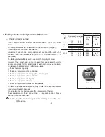
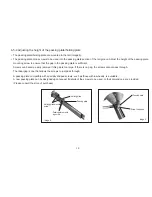

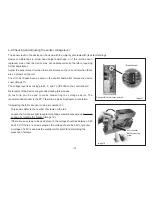


Adjusting the screw feed sensor <using pin number 5>
This sensor detects movement of the stopper.
Loosen the stopper sensor bracket mounting screws (2 places) and adjust the
light receptor in a sideways direction. (Image 19)
The sensor level is adjusted so that it is 4V or greater with the stopper in the
ON position, and 0.2V or less with the stopper in the OFF position.
A voltage of 2.5V is used as the electronic threshold for determining the
presence of screws.
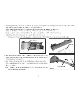
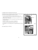
Adjusting the tip sensor <using pin number 7>
This sensor detects the presence of screws in the stopper.
Loosen the tip light receptor sensor bracket mounting screws (2 places) and
move up or down by rotating the bracket (Image 20).
If there are no screws to be used present, the voltage should be between 0.25
and 1.5V. If there are screws present, the voltage should be 3.5V or greater.
A voltage of 2.5V is used as the electronic threshold for determining the
presence of screws.
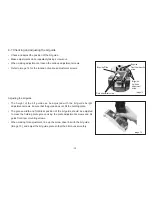
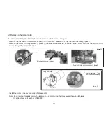
Once adjustment of each section has been completed, check the actual
operation of the device with screws to be used.
If there are any faults in the operation of the device, the adjustments above will
need to be performed again, in addition to adjusting the rail oscillation and front/
rear positioning.
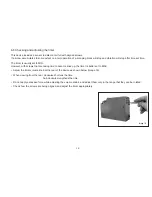
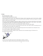
After checking the operation of the device, return all wiring to its original state.
Caution Ensure that the wiring does not become jammed or interrupt the
operation of moving parts.
Stopper sensor Bracket
Bracket mounting screw
Image 19
Mounting screws
OFF
ON
Stopper
Image 20
- 16 -


