


5.4 Creating Condition Settings Files
41
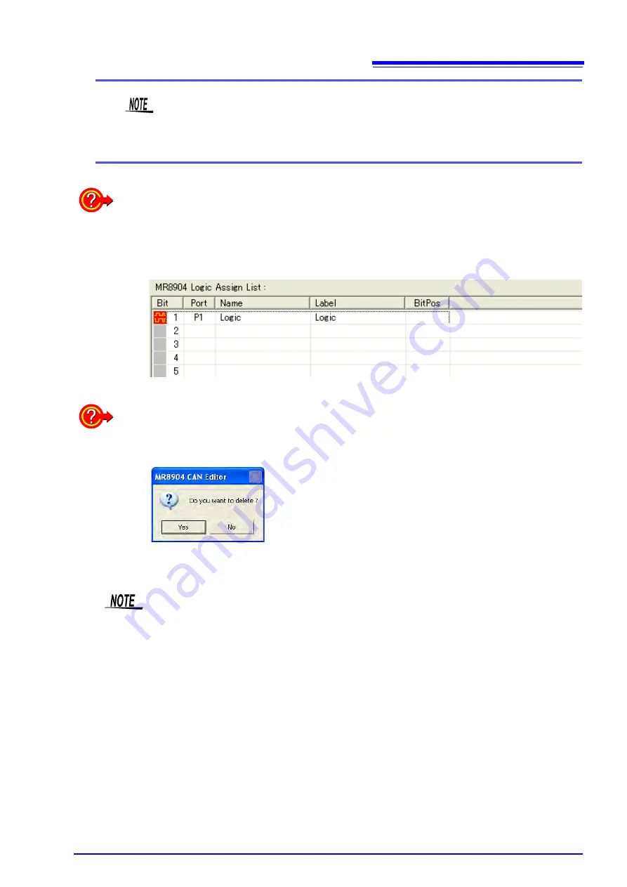
The
[MR8904 Logic Assign List]
allows data items from the
[MR8904 Register List]
to be allocated to each bit of a 16-bit signal. If the data item consists of 8 bits, 8 bits will
be automatically allocated with the bit position at which the item was dropped (1 to 16)
as the LSB.
What is an ID trigger?
You can register an ID trigger by selecting
[Assign ID]
when you drag and drop the data
item. This function outputs a high pulse to the registered logic channel when a CAN mes-
sage with the registered definition’s ID is received. When an ID trigger is registered, a red
mark will be shown for the logic channel.
Deleting data from an assign list
Right-click on the item you wish to delete to display the following message. (You can also
select multiple items and delete them at once.)
Click
[Yes]
to delete the item(s).
Up to 200
s of dead time occurs between the time the CAN message with the registered
definition’s ID is received and the time that the data is transferred to the Memory HiCorder.
If multiple CAN messages are received during the dead time, the received CAN message
may not be applied to the data.
Содержание MR8904
Страница 1: ...MR8904 Instruction Manual CAN UNIT EN Sept 2018 Revised edition 3 MR8904A981 03 18 09H...
Страница 2: ......
Страница 10: ...Usage Notes 6...
Страница 14: ...10...
Страница 24: ...3 3 Connecting the Unit to a PC 20...
Страница 66: ...7 4 MR8904 CAN Editor General Specifications 62...
Страница 69: ......
Страница 70: ......
Страница 71: ......
Страница 72: ......


