


Annex
96/98
SmartWire-DT Gateway | EU5C-SWD-ETHERCAT
DOC140901UM01EN | Revision 1 | English | 2015-03 | Released | Public
© Hilscher 2015
14 Annex
14.1 List of figures
Figure 1: Data flow EU5C-SWD-ETHERCAT Gateway
21
Figure 2: Front view EU5C-SWD-ETHERCAT gateway
26
Figure 3: LEDs EU5C-SWD-ETHERCAT Gateway
27
Figure 4: Pinning of the Ethernet interface (RJ45)
30
Figure 5:Device type label EU5C-SWD-ETHERCAT Gateway
31
Figure 6: Mounting principle of the gateway
34
Figure 7: Hook gateway to upper railing
34
Figure 8: Hook gateway to lower railing
35
Figure 9: Gateway is clamped to top hat rail
35
Figure 10: Unhook gateway
36
Figure 11: Gateway power supply
38
Figure 12: Connecting SmartWire-DT to gateway
39
Figure 13: Connecting EtherCAT network to gateway
40
Figure 14: TwinCAT start screen
46
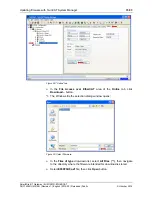
Figure 15: Installing TwinCAT Ethernet adapter (1)
47
Figure 16: Installing TwinCAT Ethernet adapter (2)
48
Figure 17: Scan devices
48
Figure 18: Message prior to device scan
49
Figure 19: New devices found dialog window
49
Figure 20: Scan for boxes
49
Figure 21: EU5C-SWD-ETHERCAT Gateway found as new box
50
Figure 22: EU5C-SWD-ETHERCAT Gateway process data (1)
51
Figure 23: EU5C-SWD-ETHERCAT Gateway process data (2)
51
Figure 24: Process data mapping in TwinCAT
52
Figure 25: Configuration data of the SWD Coordinator (gateway) in TwinCAT
53
Figure 26: Editing parameters of SWD Coordinator (1)
55
Figure 27: Editing parameters of SWD Coordinator (2)
56
Figure 28: Editing parameters of SWD Coordinator (3)
57
Figure 29: Configuration data elements of SWD devices in TwinCAT
58
Figure 30: Editing device options of SWD device (1)
61
Figure 31: Editing device options of SWD device (2)
62
Figure 32: Editing device options of SWD device (3)
63
Figure 33: “Programmer” view of Windows 7 calculator
65
Figure 34: Editing device parameters of SWD device (1)
69
Figure 35: Editing device parameters of SWD device (2)
70
Figure 36: Editing device parameters of SWD device (3)
71
Figure 37: Conducting acyclical communication
74
Figure 38: “Online” tab
85
Figure 39: Select Firmware
85
Figure 40: Edit firmware name (1)
86
Figure 41: Edit firmware name (2)
86
Figure 42: Ethernet Device Configuration Tool
88
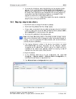
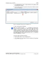
Figure 43: Found gateway in Ethernet Device Configuration Tool
89
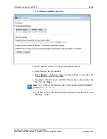
Figure 44: Firmware recovery via HTTP (as depicted in Internet Explorer)
90
Figure 45: Reset after firmware download via HTTP (as depicted in Internet Explorer)
91
Figure 46: Successful device reset message (as depicted in Internet Explorer)
92