3.2.26
Microswitches
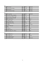
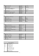
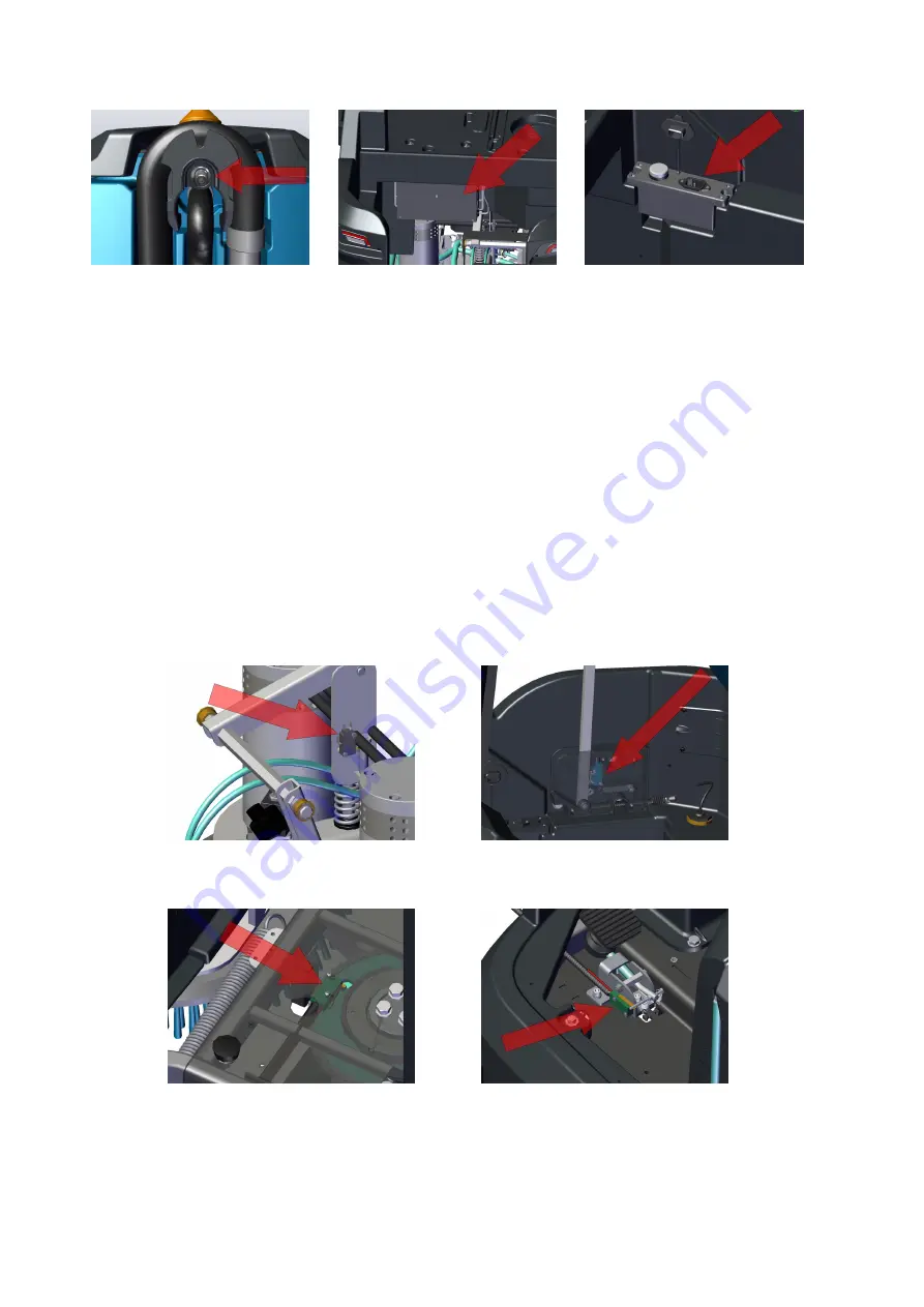
The machine is provided with a series of microswitches to enable/disable certain functions or to send signals to
the traction card. In particular:
Max pressure Micro
. The micro is mounted on a plate integral with the base of the brushdeck. In case
the motors have a too low absorption, it avoids that the deck actuator continues to push. If the rod goes
over its limit, the micro opens and stops the actuator.
Service lights Micro
. The micro is on the recovery tank support lever. When the recovery tank is
lifted, the lever allows the Micro to activate the service lights.
Curve speed reduction Microswitch
. It is positioned below the platform. After a predetermined angle
of rotation of the steering, the microswitch opens and the curve speed reduction function is activated.
The percentage of the speed reduction is an adjustable parameter.
Electronic Brake Micro
. The micro is placed under the brake pedal. When the pedal is pressed, the
braking to the Main card is required.
Electrobrake Microswitch
. The micro is assembled externally to the traction motor, and can be
disabled by a lever.
If enabled
, when the machine is switched OFF the traction is inhibited, when the
machine is ON the traction is enabled.
If disabled
, when the machine is switched OFF the machine is
not braked, when the machine is ON the traction is inhibited and the display gives an alarm.
38
Содержание 108538
Страница 1: ...SERVICE MANUAL TRIDENT R30SC R28SC Version AA Date August 5 2019 Document Number 100x...
Страница 4: ...Part I Product Introduction 4...
Страница 10: ...1 6 Machine Dimensions 1 6 1 R30SC 10...
Страница 11: ...1 6 2 R28SC 11...
Страница 15: ...Part II Anomalies Resolution Guide 15...
Страница 24: ...Part III Functional Groups 24...
Страница 26: ...3 2 Location of Electrical Components 3 2 1 R30SC R28SC Plus 26...
Страница 28: ...3 2 3 R30SC Base 28...
Страница 64: ...4 6 Related electrical circuit 4 6 1 R30SC Base 64...
Страница 66: ...4 6 2 R30SC PLUS 66...
Страница 76: ...5 6 Related electrical circuit 5 6 1 R28SC PLUS 76...
Страница 80: ...Chapter 6 Vacuum Unit 6 1 Location on machine The vacuum unit is located in central rear position 80...
Страница 84: ...6 6 Related electrical circuit 6 6 1 R28SC Base 84...
Страница 86: ...6 6 2 R30SC R28SC PLUS 86...
Страница 94: ...7 5 Related electrical circuit 7 5 1 R30SC Base 94...
Страница 96: ...7 5 2 R30SC R28SC PLUS 96...
Страница 104: ...8 5 Related electrical circuit 8 5 1 R30SC Base 104...
Страница 106: ...8 5 2 R30SC R28SC PLUS 106...
Страница 112: ...Part IV Accessories and Add On 112...


