JUNCTION
BOX
A
IR
F
LOW
, D
EFROST
& T
EMP
C
ONTROL
DEFROST & TEMPERATURE CONTROLS
OWZA cases are equipped with both Electric (low-temp) and
Timed-Off (medium-temp) defrost and can be run in either low-
or medium-temperature defrost modes. Switching between the
two different temperature modes is easily done by using a spe-
cial key switch located on the left-bottom-front of the case (see
Fig. 3).
The rear baffle (see diagram below) contains the sensor bulb
and probe for electric defrost termination; the sensor bulb for
temperature control; and the discharge air probe.
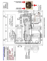
The defrost termination control thermostat and the temperature
control thermostat are located in the junction box underneath
the case on the bottom-left side (see diagram below). To ac-
cess the thermostats, you must first remove the front kick plate,
then remove the junction box cover. For instructions on remov-
Electric defrost termination sensor bulb
Electric defrost termination probe
Temperature control sensor bulb
Discharge air probe
1. DISCHARGE AIR
2. LOAD LIMIT
3. AIR CURTAIN
4. RETURN AIR
ing the front kick plate and lower front panel, see the trim out
section of this manual on page 5.
It is important to consult the control setting guidelines shown
on page 2 before setting the defrost schedule. Further adjust-
ments may be required depending on store conditions.
AIR FLOW & PRODUCT LOAD
Cases have been designed to provide maximum product capac-
ity within the refrigerated air envelope. Please keep products
within the load limit line shown on the diagram below.
It is important that you do not overload the food product display
so that it impinges on the air
fl
ow pattern. Overloading will
cause malfunction and the loss of proper temperature levels,
particularly when discharge and return air sections are covered.
1
1
4
3
2
Defrost termination control thermostat
Temperature control thermostat
LOW
TEMP
MED TEMP
Fig. 3 Low/Med Temp
keyed switch
10
Содержание OWZA
Страница 2: ...ii ...
Страница 15: ...APPENDIX A DOMESTIC WIRING DIAGRAM ...
Страница 16: ......
Страница 17: ......
Страница 18: ......
Страница 19: ......
Страница 20: ...APPENDIX B EXPORT WIRING DIAGRAM ...
Страница 21: ......
Страница 22: ......
Страница 23: ......
Страница 24: ......
Страница 25: ...APPENDIX C CONTROLLER INFORMATION ...
Страница 29: ...APPENDIX D USER SET POINTS ...
Страница 30: ......


