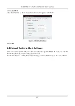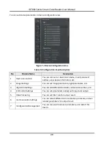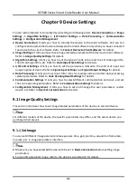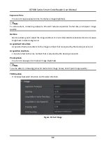
ID7000 Series Smart Code Reader User Manual
17
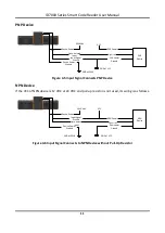
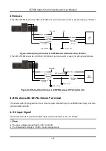
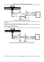
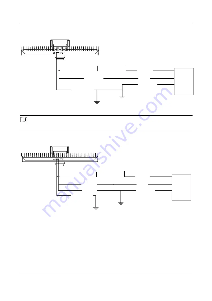
LineIn0 Wiring with PNP Device
Differential Input
0+
Device Power
PWR 48V
Device Power
Ground
PNP Device
PNP Power
PNP Power
Ground
Signal Line
VCC
GND of PWR
GND of VCC
Common
Ground
Figure 4-16 LineIn0 Wiring with PNP Device
Note
The differential input 0- signal is not used and no wiring is required.
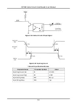
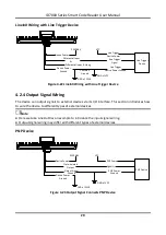
LineIn1 Wiring with PNP Device
Opto-isolated
Input
Input Common
Ground
PWR 48V
Device Power
Device Power
Ground
GND of PWR
GND of VCC
VCC
PNP Power
Signal Line
PNP Power
Ground
PNP Device
Figure 4-17 LineIn1 Wiring with PNP Device
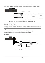
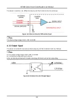
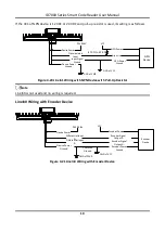
LineIn0 Wiring with NPN Device
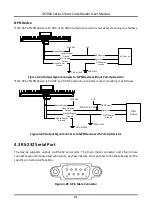
If the VCC of NPN device is 12 VDC or 24 VDC and pull-up resistor is not used, its wiring is as follows.
Содержание ID7000 Series
Страница 1: ...ID7000 Series Smart Code Reader User Manual ...
Страница 76: ...ID7000 Series Smart Code Reader User Manual 67 Figure 11 2 Reboot Device ...
Страница 80: ...UD26117B ...


