background image

ID7000 Series Smart Code Reader User Manual 

46 

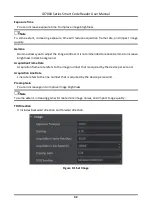
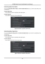
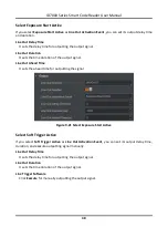
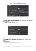
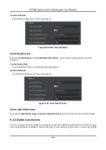
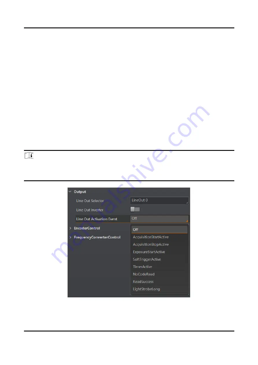
Acquisition Stop Active   

If acquisition stops, the output signal will be triggered. 

Exposure Start Active   

If the exposure starts, the output signal will be triggered. 

Soft Trigger Active   

The client software triggers the output signal. 

Timer Active   

The timer triggers the output signal. 

No Code Read   

If no code read by the device, the output signal will be triggered. 

Read Success   

If the code is read by the device, the output signal will be triggered. 

Light Strobe Long 

If the light mode is 

Strobe Long

, the output signal will be triggered. 

Note 


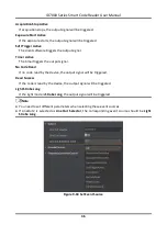
You need to set different parameters when selecting these event sources. 


If  LineOut2  is  selected  as 

Line  Out  Selector

,  the  corresponding  event  source  should  be 

Light 

Strobe Long


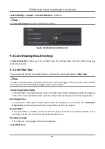
Figure 9-18 Set Event Source


Содержание ID7000 Series

Страница 1: ...ID7000 Series Smart Code Reader User Manual ...

Страница 2: ...AL CONSEQUENTIAL INCIDENTAL OR INDIRECT DAMAGES INCLUDING AMONG OTHERS DAMAGES FOR LOSS OF BUSINESS PROFITS BUSINESS INTERRUPTION OR LOSS OF DATA CORRUPTION OF SYSTEMS OR LOSS OF DOCUMENTATION WHETHER BASED ON BREACH OF CONTRACT TORT INCLUDING NEGLIGENCE PRODUCT LIABILITY OR OTHERWISE IN CONNECTION WITH THE USE OF THE PRODUCT EVEN IF HIKROBOT HAS BEEN ADVISED OF THE POSSIBILITY OF SUCH DAMAGES OR ...

Страница 3: ...rmful interference to radio or television reception which can be determined by turning the equipment off and on the user is encouraged to try to correct the interference by one or more of the following measures Reorient or relocate the receiving antenna Increase the separation between the equipment and receiver Connect the equipment into an outlet on a circuit different from that to which the rece...

Страница 4: ...result in equipment damage data loss performance degradation or unexpected results Note Provides additional information to emphasize or supplement important points of the main text Available Model This manual is applicable to the ID7000 Series Smart Code Reader Safety Instruction These instructions are intended to ensure that the user can use the product correctly to avoid danger or property loss ...

Страница 5: ...onment or high humidity environment Do not aim the product lens at objects of strong light such as the sun and incandescent lamp Otherwise the lens may be damaged The product should be stored in dry environment without corrosive gas Avoidplacing the product in direct sunlight and poorly ventilated locations or near heat sources such as heater or heating ignoring this warning may lead to fire hazar...

Страница 6: ...do not disassemble the device arbitrarily Cleaning Please do not touch the image sensor directly If the sensor needs to be cleaned please use a clean rag and wet it with alcohol then gently wipe off the dirt if the device is not in use please cover the image sensor with dust cover for protection Installation Please do not install the product on vibrating surface or places that are vulnerable to im...

Страница 7: ...vice with 12 Pin M12 Connector 8 4 1 1 Input Signal 8 4 1 2 Output Signal 9 4 1 3 Input Signal Wiring 10 4 1 4 Output Signal Wiring 12 4 2 Device with 10 Pin Green Terminal 13 4 2 1 Input Signal 13 4 2 2 Output Signal 15 4 2 3 Input Signal Wiring 16 4 2 4 Output Signal Wiring 20 4 3 RS 232 Serial Port 21 Chapter 5 Installation 23 5 1 Installation Preparation 23 Chapter 6 Device Connection 24 6 1 S...

Страница 8: ...ameter 35 9 3 Signal Input Settings 38 9 3 1 Internal and External Trigger Mode 38 9 3 2 Enable Internal Trigger Mode 39 9 3 3 Enable External Trigger Mode 39 9 3 4 Set Trigger Mode 39 9 3 5 Set Shaft Encoder Control 42 9 3 6 Set Frequency Converter Control 44 9 4 Signal Output Settings 45 9 4 1 Select Output Signal 45 9 4 2 Set Event Source 45 9 4 3 Enable Line Inverter 50 9 5 Code Reading Result...

Страница 9: ...11 Device Maintenance 66 11 1 Update Firmware 66 11 2 Reboot Device 66 Chapter 12 FAQ Frequently Asked Question 68 12 1 Why there is no device listed after I run the client software 68 12 2 Why the image is very dark 68 12 3 Why the image quality is very poor during the live view 68 12 4 Why there is no image in the live view 69 12 5 Why the recognized codes are opposite in direction with actual o...

Страница 10: ... and set different parameters 1 2 Key Features Built in code reading algorithm to read different types of one dimensional and two dimensional codes with good robustness Supports image stitching and outputting combined images according to order Adopts image sensor to acquire and provide high quality images Supports different trigger modes and image acquisition modes Adopts multiple IO interfaces fo...

Страница 11: ...er Manual 2 Chapter 2 Appearance Note Appearance here is for reference only Refer to the device s specification for detailed dimension information 1 4 2 5 4 4 4 6 8 9 9 9 9 5 5 5 7 10 10 3 2 3 Figure 2 1 Device with 12 Pin M12 Connector ...

Страница 12: ...ries Smart Code Reader User Manual 3 4 4 2 3 6 8 5 5 1 10 10 Figure 2 2 Device with 10 Pin Green Terminal and F Lens Mount 5 5 1 10 10 4 4 2 3 6 8 Figure 2 3 Device with 10 Pin Green Terminal and M42 Lens Mount ...

Страница 13: ...ply is 48 VDC 4 Screw Hole It is used to fix the device You should use supplied M6 screws in the package 5 Screw It is used to fix the device body and the front rear cover 6 Gigabit Ethernet Interface It refers to the gigabit Ethernet interface for transmitting data 7 Screw Hole of GigE Interface It is used to fix the network cable 8 Indicator It indicates the operating status of the device Refer ...

Страница 14: ... 8 9 1 10 11 12 Figure 3 1 12 Pin M12 Connector Refer to the pin definitions below and labels attached to the I O cable to wire the device Table 3 1 Pin Definitions of 12 Pin M12 Connector No Signal I O Signal Source Description 1 Reversed 2 Reversed 3 OPTO_OUT0 LineOut0 signal line Opto isolated output 0 4 OPTO_OUT1 LineOut1 signal line Opto isolated output 1 5 OPTO_OUT2 It controls the device s ...

Страница 15: ...l port signal Figure 3 2 10 Pin Green Terminal Table 3 2 Pin Definitions of 10 Pin Green Terminal No Signal I O Signal Source Description 1 OPTO_OUT0 LineOut0 signal line Opto isolated output 0 2 OPTO_OUT1 LineOut1 signal line Opto isolated output 1 3 GND RS 232 serial port ground 4 OUT_COM LineOut0 1 signal ground Output common terminal 5 OPTO_IN0 LineIn0 signal line Differential input 0 6 OPTO_I...

Страница 16: ...dicator Indicator Color Device Status Solution Unlit Power supply exception occurs Check the wiring of the power supply cable Solid blue The device runs normally Network exception occurs Check the network cable wiring The device s software is not started Restart the device The device exception occurs Restart the device and check its firmware version ...

Страница 17: ...l have different I O electrical features and wiring 4 1 Device with 12 Pin M12 Connector The device with 12 pin M12 connector has three opto isolatedinputs and two opto isolated outputs 4 1 1 Input Signal The device s LineIn 0 1 2 are opto isolated inputs and their internal circuit is as follows Note The input voltage ranges from 5 VDC to 30 VDC The breakdown voltage is 36 VDC Keep voltage stable ...

Страница 18: ...el High VH 2 VDC Input Falling Delay TDF 81 6 μs Input Rising Delay TDR 7 μs 4 1 2 Output Signal The device s LineOut 0 1 are opto isolated outputs and their internal circuit is as follows Note The output voltage ranges from 5 VDC to 30 VDC The maximum output current is 45 mA Do not directly connect with inductive load e g DC motor etc when outputting Figure 4 3 Internal Circuit of Output Signal ...

Страница 19: ...ing Delay TDF 6 3 μs Output Rising Delay TDR 68 μs Output Falling Time TF 3 μs Output Rising Time TR 60 μs Note If the external voltage and resistance change the corresponding current of output signal and output logic level low may differ 4 1 3 Input Signal Wiring The device can receive external input signal via itsI O interface This section introduces how to wire the device to different types of ...

Страница 20: ...und GND of VCC Figure 4 5 Input Signal Connects PNP Device NPN Device If the VCC of NPN device is 12 VDC or 24 VDC and pull up resistor is not used its wiring is as follows Opto isolated Input Device Power PWR 48V Device Power Ground NPN Device NPN Power NPN Power Ground Signal Line VCC GND of PWR Input Signal Ground GND of VCC Figure 4 6 Input Signal Connects to NPN Device without Pull Up Resisto...

Страница 21: ...th Pull Up Resistor 4 1 4 Output Signal Wiring The device can output signals to external devices via its I O interface This section introduces how to wire the device to different types of external devices Note Here we take LineOut0 as an example to introduce the input signal wiring Output signal wiring may differ with different types of external devices PNP Device Opto isolated Output Device Power...

Страница 22: ... resistor is used its wiring is as follows Opto isolated Output Device Power PWR 48V Device Power Ground NPN Device NPN Power NPN Power Ground Signal Line VCC GND of PWR Output Signal Ground GND of VCC 470 Ω to 4 7 KΩ Figure 4 10 Output Signal Connects to NPN Device with Pull Up Resistor 4 2 Device with 10 Pin Green Terminal The device with 10 pin green terminal has one opto isolated input one dif...

Страница 23: ...Internal Circuit of Input Signal Figure 4 12 Input Logic Level Table 4 3 Input Electrical Feature Parameter Name Parameter Symbol Value Input Logic Level Low VL 1 5 VDC Input Logic Level High VH 2 VDC Input Falling Delay TDF 81 6 μs Input Rising Delay TDR 7 μs ...

Страница 24: ...Input Note The input voltage ranges from 5 VDC to 30 VDC 4 2 2 Output Signal The device s LineOut 0 1 are opto isolated outputs and their internal circuit is as follows Note The output voltage ranges from 5 VDC to 30 VDC The maximum output current is 45 mA Do not directly connect with inductive load e g DC motor etc when outputting Figure 4 14 Internal Circuit of Output Signal ...

Страница 25: ...gic Level High VH 3 2 VDC Output Falling Delay TDF 6 3 μs Output Rising Delay TDR 68 μs Output Falling Time TF 3 μs Output Rising Time TR 60 μs Note If the external voltage and resistance change the corresponding current of output signal and output logic level low may differ 4 2 3 Input Signal Wiring The device can receive external input signal via itsI O interface This section introduces how to w...

Страница 26: ...g with PNP Device Note The differential input 0 signal is not used and no wiring is required LineIn1 Wiring with PNP Device Opto isolated Input Input Common Ground PWR 48V Device Power Device Power Ground GND of PWR GND of VCC VCC PNP Power Signal Line PNP Power Ground PNP Device Figure 4 17 LineIn1 Wiring with PNP Device LineIn0 Wiring with NPN Device If the VCC of NPN device is 12 VDC or 24 VDC ...

Страница 27: ...vice Note The differential input 0 signal is not used and no wiring is required LineIn1 Wiring with NPN Device If the VCC of NPN device is 12 VDC or 24 VDC and pull up resistor is not used its wiring is as follows PWR 48V Device Power Input Common Ground Opto isolated Input Device Power Ground VCC NPN Device NPN Power Signal Line NPN Power Ground GND of PWR GND of VCC Figure 4 19 LineIn1 Wiring wi...

Страница 28: ...PWR Input Signal Ground GND of VCC 470 Ω to 4 7 KΩ Figure 4 20 LineIn1 Wiring with NPN Device with Pull Up Resistor Note LineIn0 is not used and no wiring is required LineIn0 Wiring with Encoder Device PWR 48V Device Power VCC Differential Input 0 Differential Input 0 Device Power Ground Common Ground GND of PWR GND of VCC Encoder Device Encoder Power Encoder Signal Output A Encoder Signal Output ...

Страница 29: ... Device 4 2 4 Output Signal Wiring The device can output signals to external devices via its I O interface This section introduces how to wire the device to different types of external devices Note Here we take LineOut0 as an example to introduce the input signal wiring Output signal wiring may differ with different types of external devices PNP Device Opto isolated Output Output Signal Ground PWR...

Страница 30: ...f NPN device is 12 VDC or 24 VDC and pull up resistor is used its wiring is as follows Opto isolated Output Device Power PWR 48V Device Power Ground NPN Device NPN Power NPN Power Ground Signal Line VCC GND of PWR Output Signal Ground GND of VCC 470 Ω to 4 7 KΩ Figure 4 25 Output Signal Connects to NPN Device with Pull Up Resistor 4 3 RS 232 Serial Port The device supports output via RS 232 serial...

Страница 31: ...eceive data 3 TX Send data 5 GND Signal ground 25 Pin Male Connector 2 TX Send data 3 RX Receive data 7 GND Signal ground You can refer to the serial port wiring below to connect the device with an external device RS 232 Input Device Power PWR 48V Device Power Ground External Device TX External Device Power Ground RX RS 232 Output GND Figure 4 28 RS 232 Serial Port Wiring ...

Страница 32: ... the package 2 Network Cable 1 The supplied gigabit Ethernet cable 10 meters 3 DC Switch Power Supply 1 The supplied DC switch power supply of 48 VDC above 5 A 4 Power Supply Cable 1 The supplied power supply cable with DC connector 10 meters 5 Lens 1 The supplied lens 6 Reflector 1 When using the device you need to have a reflector to read codes on the bottom It is sold separately Refer to the im...

Страница 33: ...e running of the client software and data transmission 6 1 1 Turn off Firewall Steps Note For different Windows versions the path name or interface may differ Please refer to the actual condition 1 Go to Windows Firewall Windows XP system Click Start Control Panel Security Center Windows Firewall Windows 7 system Click Start Control Panel Windows Firewall Windows 10 system Click Start Control Pane...

Страница 34: ...enter Change adapter settings 2 Select NIC and set the IP obtainment mode Select Obtain an IP address automatically to get an IP address of the PC automatically Or select Use the following IP address to set an IP address for the PC manually Figure 6 2 Set PC Network 3 Set NIC property 1 Go to NIC settings page Control Panel Hardware and Sound Device Manager Network Adapter 2 Select corresponding n...

Страница 35: ...rsions of client software you use 1 Double click the installation package to start installing the client software 2 Select the language 3 Read and check Terms of the License Agreement 4 Click Start Setup 5 Select installation directory and click Next Figure 6 3 Installation Interface 6 Finish the installation according to the interface prompts 6 3 Set Device Network You can set and operate the dev...

Страница 36: ... the PC Figure 6 4 Modify IP Address 6 Click OK 6 4 Connect Device to Client Software Make sure your device IP address is in the same network segment with the PC where you installed the client software before connecting the device to it Double click the device in the device list or click to connect the device to the client software ...

Страница 37: ...Toolbar The control toolbar provides quick operations for the device You can click different icons to start or stop batch acquisition change window layout view statistics information and device log 3 Device Configuration Area You can connect or disconnect device set parameters and modify device IP address in this area 4 Live View Window This area displays the acquisition images and algorithm readi...

Страница 38: ...ce information etc 2 Image Settings You can set image parameters light parameters etc 3 Algorithm Settings You can add different barcodes set barcode number etc 4 I O Control Settings You can set parameters related with input and output 5 Data Processing You can set filter rule for output result 6 Communication Settings You can select different communication protocols and set related parameters fo...

Страница 39: ...evice Mode Table 8 1 Device Mode Description Device Mode Description Test Mode It is used during device debugging The device outputs images that are acquired in real time and displays code information Normal Mode It is used during device normal operation After reading code in image the device outputs image and code information Raw Mode It is used during testing image data The device outputs raw da...

Страница 40: ...nd output signals of device Refer to Signal Input Settings and Signal Output Settings for details Data Processing It tells you how to set filter rules for reading codes and other data processing related parameters Refer to Code Reading Result Settings for details Communication Settings It tells you how to select different communication protocols and set their corresponding parameters Refer to Comm...

Страница 41: ...e Gamma to increase brightness in dark background Acquisition Frame Rate Acquisition frame rate refers to the image number that is acquired by the device per second Acquisition Line Rate Line rate refers to the line number that is acquired by the device per second Preamp Gain You can increase gain to improve image brightness Note To some extent increasing gain will create more image noises and imp...

Страница 42: ...tion and the unit is μs Lighting Out Delay Time It sets the delay time for lighting after exposure and the unit is μs Line Out Ahead Time It determines how earlier the light source starts lighting before exposure and the unit is μs Figure 9 2 Set Light Source 9 2 Code Algorithm Settings The device supports reading multiple types of 1D code and 2D code and you can add and set code parameters via th...

Страница 43: ...me Note that selecting more symbologies or adding more codes may consume more time to recognize codes in the image No matter 1D code or 2D code up to 20 codes can be added at a time Note that adding more codes may consume more time to recognize codes in the image Therefore the code number is recommended to be set according to the actual demands The device may output actual code number when the mis...

Страница 44: ...configured Code 39 Check Enable this parameter if Code 39 uses the parity bit Note You need to select Code 39 in Add Barcode ITF 25 Check Enable this parameter if ITF 25 uses the parity bit Note You need to select ITF 25 in Add Barcode Code Score Enable If it is enabled the device will evaluate code quality and display overall grade and code score in history record area of the client software The ...

Страница 45: ...alue Mirror Mode It is useful when the recognized image is a mirror one mirroring in X coordinate 3 modes are available Non Mirror 0 Mirror 1 and Adaptive 2 Downsampling Level It refers to the pixel sample size that the code reader takes Increasing this parameter willimprove the code reading efficiency at the expense of code recognition rate Note Increasing this parameter value will improve the co...

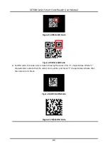
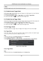
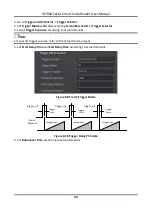
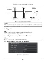
Страница 46: ... Figure 9 5 Black QR Code For DM code the code color is determined by the color of its L shaped sides White L shaped sides indicate that the code color is white and black L shaped sides indicate that the code color is black Figure 9 6 White DM Code Figure 9 7 Black DM Code ...

Страница 47: ...des in the image Advance Param This parameter is applicable to some special codes and it is recommended to use the default value DM Code Shape It defines the recognizable code shape Square 0 stands for square mode If the 2D code is square shaped it can be recognized by the device Rectangle 1 stands for rectangle mode If the 2D code is rectangle shaped it can be recognized by the device Adaptive 2 ...

Страница 48: ...enable the external trigger mode Click I O Control Settings Input Trigger Mode and select On as Trigger Mode In the live view page click to enable the external trigger mode 9 3 4 Set Trigger Mode The device supports free trigger mode line trigger frame trigger and line plus frame trigger Free Trigger Mode In the free trigger mode the device generates trigger signals by itself and outputs images co...

Страница 49: ...ing to actual demands Note For specific trigger sources refer to the actual device you got 5 Set Start Delay Time and End Delay Time according to actual demands Figure 9 9 Frame Trigger Mode Sensor Exposure Integration1 Integration2 Integration3 Trigger_in1 Trigger Delay Trigger_in2 Trigger Delay Trigger_in3 Trigger Delay Figure 9 10 Trigger Delay Principle 6 Set Debouncer Time according to actual...

Страница 50: ...debouncer time is larger than the pulse width of trigger signal the trigger signal will be ignored Otherwise the trigger signal will be outputted after delay Line Trigger Mode Steps 1 Right click the device in the Device Connection and click Feature Tree 2 Go to Trigger and IO Control Trigger Selector 3 Set Trigger Mode as On after selecting Line Start as Trigger Selector 4 Select Trigger In Sourc...

Страница 51: ... details 7 You need to set related parameters of frequency converter control in Frequency Converter Control after selecting Frequency Converter as Trigger In Source Refer to section Set Frequency Converter Control for details Line Frame Trigger Mode In this trigger mode both line trigger and frame trigger are enabled The device image acquisition is controlled by frame trigger signal and line trigg...

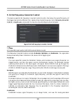
Страница 52: ...ut pulse acts as a trigger signal for the device Synchronize acquisition speed and sample movement of device Non uniform motion can also be a perfect match A trigger signal can be set as acquiring multiple lines or multiple frames with adjustable ratio You should go to Encoder Control to select the signal source of signal A and signal B via Encoder Source A and Encoder Source B Figure 9 15 Set Enc...

Страница 53: ... and signals above 100 kHz must go through the PreDivider module to reduce the frequency for the Multiplier can only receive signals in the range of 10 Hz to 100 kHz frequency range The periodic jitter of shaft encoder signal is accepted Multiplier After the signal is processed by the PreDivider it is sent to the Multiplier The Multiplier multiplies the signal by an integer to increase its signal ...

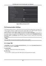
Страница 54: ...f controlling light source mode Figure 9 17 Select Output Signal 9 4 2 Set Event Source Note The event source parameters may differ by device model The device supports outputting different trigger signals according to the event source you select Click I O Control Settings Output Line Out Activation Event to select event source The device supports following event sources including Acquisition Start...

Страница 55: ...e timer triggers the output signal No Code Read If no code read by the device the output signal will be triggered Read Success If the code is read by the device the output signal will be triggered Light Strobe Long If the light mode is Strobe Long the output signal will be triggered Note You need to set different parameters when selecting these event sources If LineOut2 is selected as Line Out Sel...

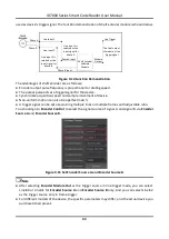
Страница 56: ...he output signal Line Out Duration It sets the time duration of the output signal Figure 9 19 Select Acquisition Start Active Select Acquisition Stop Active If you select Acquisition Stop Active as Line Out Activation Event you can set its output delay time and duration Line Out Delay Time It sets the delay time for outputting the output signal Line Out Duration It sets the time duration of the ou...

Страница 57: ... output signal Line Out Ahead Time It sets the ahead time for outputting the signal Figure 9 21 Select Exposure Start Active Select Soft Trigger Active If you select Soft Trigger Active as Line Out Activation Event you can set its output delay time duration and execute outputting signal manually Line Out Delay Time It sets the delay time for outputting the output signal Line Out Duration It sets t...

Страница 58: ...tput duration and period Line Out Duration It sets the time duration of the output signal Line Out Period It sets the time period of the output signal Figure 9 23 Select Timer Active Select No Code Read If you select No Code Read as Line Out Activation Event you can set its output delay time and duration Line Out Delay Time It sets the delay time for outputting the output signal ...

Страница 59: ... the delay time for outputting the output signal Line Out Duration It sets the time duration of the output signal Figure 9 25 Select Read Success Select Light Strobe Long If you select Light Strobe Long as Line Out Activation Event you do not need to set any parameters 9 4 3 Enable Line Inverter The line inverter function allows the device to invert the electrical signal level of an I O line and m...

Страница 60: ...de you select Here we take normal device mode and internal trigger mode as an example Instant Output Mode Enable If this parameter is enabled the device can instantly output code reading result when recognizing codes If it is not enabled the device will not output code reading result until the trigger stops Min Output Time It sets the min waiting time before data output For example if you set 500 ...

Страница 61: ...he codes which contain a specific regular expression You can enter the specific regular expression in Regular Expression Filter Min Code Length If the length of a barcode is shorter in terms of the number of characters contained in the barcode than the configured value the device will not parse the contents of the barcode The valid value is from 1 to 256 For example if you set the value as 6 the d...

Страница 62: ...g parameters Note The supported communication protocols may differ by device models Result format settings are only available if you select TCP Client TCP Server Serial and FTP as the communication protocol when the device mode is Normal Result format settings are not available for Smart SDK and HTTP For details about communication protocol see section Communication Settings for details Result Out...

Страница 63: ...er to the actual device you got for details NoRead Image Index It sets the specific image that is outputted when no code information is read For example if you set this parameter as 5 and the 5th image will be output TCP Output Barcode Name Enable If this parameter is enabled the outputted code information will contain the name of the code TCP Output Barcode Position Enable If this parameter is en...

Страница 64: ...It refers to the delimiter that separates code name position angle package ID etc You can set it according to actual condition Figure 9 29 Result Output via TCP Client Result Output via FTP If FTP is selected as Communication Protocols you need to set following parameters Note The configurable parameters may differ by the trigger mode and here we take the external trigger mode as an example NoRead...

Страница 65: ...only upload the content of the code Just Picture refers to only upload the code picture Result and Picture refers to upload both the content of the code and the picture FTP Image Format It sets the format of the picture uploaded to FTP server Note The device currently support JPG format only FTP File Default Name It refers to the default name of the file uploaded to FTP server You can set it accor...

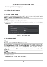
Страница 66: ... only supports SmartSDK protocol and no parameter settings are required While in Normal mode the device supports SmartSDK TCP Client Serial FTP HTTP and TCP Server communication protocols and you need to set corresponding parameters Note The supported communication protocols may differ by device models 9 6 1 Smart SDK If Smart SDK is selected as the Communication Protocols you can enable SmartSdk ...

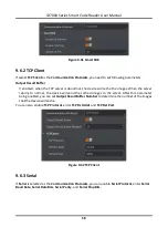
Страница 67: ... server returns to normal the device will send the cached images to the server After this parameter being enabled you can set Output Result Buffer Number to determine the number of the images that the device will cache You can also enable TCP Protocol enter TCP Dst Addr and TCP Dst Port Figure 9 32 TCP Client 9 6 3 Serial If Serial is selected as the Communication Protocols you can enable Serial P...

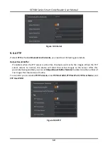
Страница 68: ...server is abnormal the device will cache the images When the FTP server returns to normal the device will send the cached images to the server After this parameter being enabled you can set Output Result Buffer Number to determine the number of the images that the device will cache You can also you can enable FTP Protocol enter FTP Host Addr FTP Host Port FTP User Name and FTP User PWD Figure 9 34...

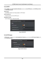
Страница 69: ...Refresh Cycle HTTP Server If enabled the device will output data via HTTP server HTTP Server Port Enter the port No of the HTTP server WebRefresh Cycle Set the frequency to refresh the Web Figure 9 35 HTTP 9 6 6 TCP Server If TCP Server is selected as the Communication Protocols you can enable TCP Server Enable and enter TCP Server Port Figure 9 36 TCP Server ...

Страница 70: ...ettings and click UserSet1 UserSet2 or UserSet3 to save the current device settings Load Settings You can load the user set to restore the device to the saved group of parameter values again if required Go to Config Management Load Settings and click Default UserSet1 UserSet2 or UserSet3 to load settings Note The Default refers to restore the device parameter settings to the factory ones Start Set...

Страница 71: ...uired before device operation 10 1 Live View You can view the real time image in the live view window Click in live view window to start live view or click to stop Figure 10 1 Live View 10 2 Enable Acquisition Enabling acquisition allows the device to acquire the real time stream Click in live view window to start acquisition or click to stop You can also right click the device on the device list ...

Страница 72: ...w to add cross line and click beside to open the editing window to set cross line parameters Figure 10 3 Add Cross Line 10 4 Start Recording During live view you can record video files and capture images continuously Note Enabling acquisition is required before recording Click in live view window to start recording and click the icon again to stop You can also click beside and then click to captur...

Страница 73: ...on mode You can click Custom to customize window division as you desired Figure 10 5 Split Window 10 6 View Reports During acquisition or live view you can view the reading status of the device Click in control toolbar to open the statistics window to view the detailed information Read Code Images refers to the number of the images on which the codes are read by the device Unread Code Images refer...

Страница 74: ...ice log window and you can view different types of logs including device errors warning and informational log etc Figure 10 7 View Log 10 8 Enable Device Auto Work This function allows the device to automatically enter the operating status after being powered on You can go to Config Management Device Auto Work Enable and enable Device Auto Work Enable Figure 10 8 Enable Device Auto Work ...

Страница 75: ...vice will reboot automatically after updating the firmware Select the device to be updated in the device list right click the device and click Firmware Update Click to select update file from local PC and click Update to update firmware Note You can also go to Tool Firmware Updater to update firmware Figure 11 1 Update Firmware 11 2 Reboot Device You can reboot the device via client software in 2 ...

Страница 76: ...ID7000 Series Smart Code Reader User Manual 67 Figure 11 2 Reboot Device ...

Страница 77: ... be connected to the network normally PC port and the device are in the same network segment 12 2 Why the image is very dark Reason Insufficient brightness of supplement light due to the small distance between conveyer belts Solution Increase the distance between conveyer belts It is recommended to have the distance of 30 mm at least 12 3 Why the image quality is very poor during the live view Rea...

Страница 78: ...es Reason Inconsistency between TDI Direction settings and the running direction of the conveyer belt and the direction that device captures images Solution Go to Feature Tree Image Settings TDI Direction and set the TDIDirection according to actual demands If the running direction of the conveyer belt is the same with the direction that device captures images and select Forward Direction as TDI D...

Страница 79: ...l length for code reading Reason The static debugging of the deviceis very inconvenient because the image acquisition is ina dynamic way Besides regarding code recognition the code definition requirementsof different mils are also different Solution Find three codes that need to be recognized codes with the lowest density and place codes facing down on the left middle and right of the conveyor cod...

Страница 80: ...UD26117B ...
Отзывы: