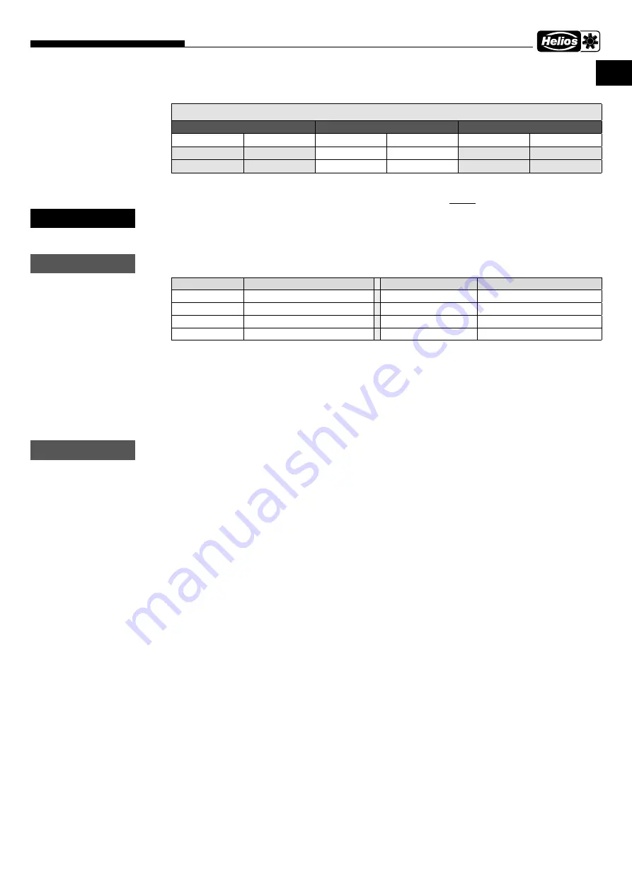
3 .6 Maximum permissible vibration limits pursuant to ISO 14694 / ISO 10816-3
– Installation of a vibration monitoring system
in explosion-proof version (on site)
The installation of a vibration monitoring system must be carried out on the outside of the fan casing.
The air gap (see Fig .7) must not be affected by the installation of the vibration monitoring system!
3 .7 Recommended tightening torque for mounting screws
The following tightening torques for mounting screw and nut connections (strength class 8.8) must be used:
The impeller fastening to the motor shaft is secured against loosening with thread-locking fluid in the factory .
3 .8 Functional safety - Emergency operation
When using the fan in important technical supply function, the system must be designed in such a way that automatic
emergency operation is guaranteed in case of a fan failure. Suitable solutions include e.g. parallel operation of two less
powerful units with a separate electric circuit, standby fan, alarm devices and emergency ventilation systems.
3 .9 Electrical connection
Before any maintenance or installation work or before opening the terminal compartment, the device must be
fully isolated from the power supply and secured against unintended restart!
– The regulations for avoiding an ignition hazard due to electrostatic discharges (TRGS 727) must be implemented.
– The electrical connection must only be carried out by a qualified electrician in accordance with the data in the termi-
nal box and enclosed wiring diagrams.
– The relevant standards, safety regulations (e.g. DIN VDE 0100) and technical connection conditions of the electricity
supply companies must be strictly observed.
– An all-pole mains switch / isolator switch with a contact opening of at least 3 mm (VDE 0700 T1 7.12.2 / EN 60335-
1) is mandatory.
– Every motor must have a
motor protection device
of category II (2)G, see Directive 2014/34/EU (Product
Safety Act), which must be adjusted to the rated current of the motor and trip within the time tE specified on the
motor type plate, provided the motor is blocked. The function must be tested on the basis of the tripping charac-
teristic line enclosed with the protection switch. Also observe the regulations especially enclosed with the device.
– Electrical connection data must correspond to the motor type plate data.
– The installation of the power cable is to be carried out professionally! The introduction of the connecting cable into
the fan must compensate the movement by the vibration dampers. The connecting cable must not touch sharp
objects.
– Only explosion-proof cable glands must be used for cable entries and connections!
– Three-phase current types must be connected by interchanging two phases for counter-clockwise rotation in the
clockwise rotating field.
– Safety components, e.g. protection grilles, must not be dismantled, bypassed or disabled.
– For further operations see the following section “Commissioning”.
– Earth connections, including any supplementary equipotential bonding, must be properly installed!
3 .10 Commissioning
The following checks must be carried out before initial commissioning:
– Check that fan operation corresponds with intended purpose
– Compare power supply voltage with rating plate data
– Check fan for solid mounting and professional electrical installation
– Check all parts especially screws, nuts and protection grilles for tight fit. Do not loosen screws in the process!
– Check unhindered movement of impeller and minimum air gap
– Check that direction of rotation and air flow direction correspond. Check direction of rotation of impeller (by acti-
vating for a short time; wear protective goggles when checking the direction of rotation)
– Compare power consumption with rating plate data
– Test functionality of motor protection device
– Test protective conductor connection
– Check sealing of the connection cable and tight clamping of cable wires
– Commissioning may only take place if protection against contact is guaranteed
Max. permissible vibration limits for fan output < 75 kW
Commissioning
Alarm
Deactivation
Firmly mounted Flexible installation Firmly mounted Flexible installation Firmly mounted Flexible installation
[mm/s]
[mm/s]
[mm/s]
[mm/s]
[mm/s]
[mm/s]
4 .5
6 .3
7 .1
11 .8
9 .0
12 .5
WARNING
m
ATTENTION
m
Screw size
Tightening torque
VERBUS RIPP
Tightening torque
M8
20 Nm
M8
25 Nm
M10
35 Nm
M10
49 Nm
M12
60 Nm
M12
86 Nm
M16
150 Nm
M16
210 Nm
ATTENTION
m
7
MegaBox MB
– Centrifugal fans
Installation and Operating Instructions
EN
Содержание MegaBox MB
Страница 15: ...13 MegaBox MB Radialventilatoren Montage und Betriebsvorschrift DE...
Страница 29: ...13 MegaBox MB Centrifugal fans Installation and Operating Instructions EN...
Страница 30: ...14 MegaBox MB Centrifugal fans Installation and Operating Instructions EN...
Страница 31: ...15 MegaBox MB Centrifugal fans Installation and Operating Instructions EN...


