HEIDENHAIN ND 1200 - V2.16 Скачать руководство пользователя страница 46

46

1 Operation

1

.4 Measur

ing P

a

rt

 F

e

at

ur

es

Measuring angles

A minimum of 4 points evenly divided on two legs of an angle are 
required to measure an angle. A maximum of 100 points can be 
probed on the two angle legs. Once the minimum two points are 
probed on each angle leg, additional points can be distributed between 
the two legs in any proportion. For example, the first leg could be 
defined by 4 points, and the second by 8.

U

Press the ANGLE MEASUREMENT key. The Probe 

Angle screen will be displayed. Press the key twice to 
measure a series of angles using auto repeat.

U

Move the stage to position the crosshairs over a 

minimum of two points evenly distributed on one 
angle leg, pressing the ENTER key to collect each 
point. 

U

Press the finish key to complete the measurement of 

the first leg.

U

Move the stage to position the crosshairs over a 

minimum of two points evenly distributed on the 
second angle leg, pressing the ENTER key to collect 
each point. 

U

Press the FINISH key to complete the angle 

measurement. The angle and angle vertex position 
will be shown. The angle feature and two angle leg 
features will be added to the feature list.

U

Press the CHANGE soft key to change the angle type 

if desired.

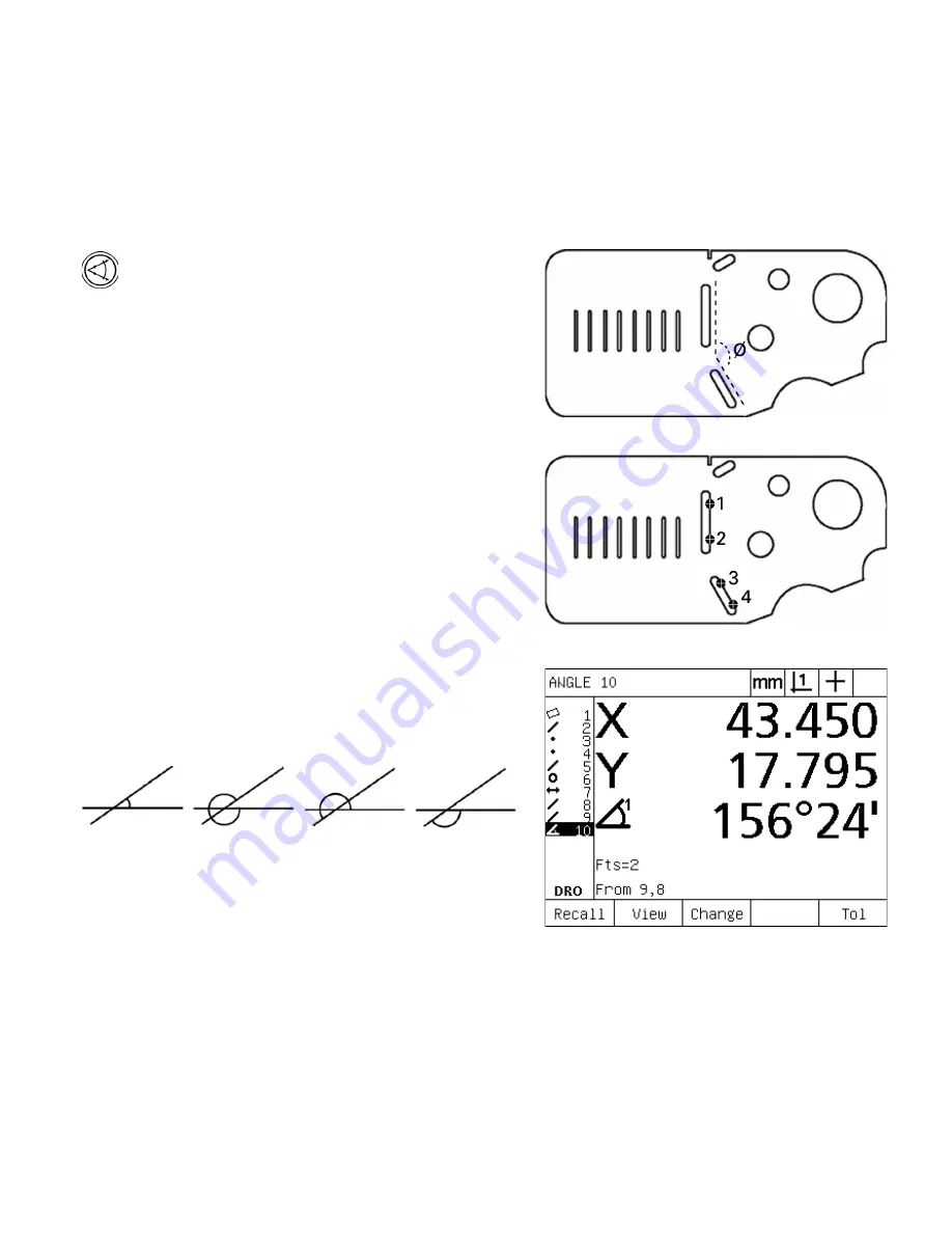
Angle types include:

„

INCLD: Included angle (A1).

„

360-A1: 360 degrees - included angle.

„

180+A1: 180 d included angle.

„

180-A1: 180 degrees - included angle

Slot features form an angle (

ø

on the part

The two legs of an angle are probed on the part

The angle and angle vertex position are shown. The 
angle and angle legs are added to the feature list

INCLD (A1)

360 - A1

180 + A1

180 - A1

Содержание ND 1200 - V2.16

Страница 1: ...Operating Instructions ND 1200 QUADRA CHEK Software Version 2 16 English en 4 2009...

Страница 2: ......

Страница 3: ...ast track keys 10 Numeric keypad 11 Send key 12 LCD On Off key Panel function key Panel key Soft keys Functions change in support of the activities displayed on the LCD Measure keys Select a feature m...

Страница 4: ...part By default the left fast track key is assigned the Enter key function and the right is assigned the Finish key function Users can program either fast track key as described later in the Hotkeys p...

Страница 5: ...ground access 5 Measurement axis connectors 6 RS 232 serial port connector 7 Optical reference cable connector 8 Optical sensor cable connector 9 Not supported in the ND 1200 10 Tilt base mechanical...

Страница 6: ...o measure part features and complete other tasks These sequences are indicated using text as shown in the following example Press the MENU key press the EDGE soft key and then press the AUTO E soft ke...

Страница 7: ...ater in chapter 2 Cleaning Use only a cloth dampened with water and a mild detergent for cleaning the exterior surfaces Never use abrasive cleaners and never use strong detergents or solvents Only dam...

Страница 8: ...8 Preface...

Страница 9: ...Toggle between forward and backward annotation 31 Select a probe type 32 Select crosshairs 32 Select an optical edge probe 32 Calibrate the optical edge detector 33 Perform a Teach 33 Perform a D Cal...

Страница 10: ...es 55 Example of applying a tolerance 56 1 8 Programming 58 ND 1200 programs 58 Recording a program 58 Example of recording a program 59 Running a program 60 Example of running a program 61 Editing a...

Страница 11: ...lation 78 Assembling the mounting stand 78 Benchtop location and mounting 78 Arm mounting optional 79 Connecting power 80 Connecting encoders 81 Connecting a computer 82 Connecting a headphone 82 Conn...

Страница 12: ...by measuring points on a calibration grid 108 NLEC by importing an nlec txt file 110 Saving NLEC correction data as an nlec txt file 110 Measurement scaling for parts that expand or shrink 111 Scale F...

Страница 13: ...Operation...

Страница 14: ...der LCD change to support different user activities Arrow cursor keys for easy navigation of lists and menus Measurement support function keys clearly marked with Unit of measure mm or inch Datum 1 or...

Страница 15: ...used to Perform measurements Apply tolerances Report results Reports of measurement results printed to USB printer sent to PC over RS 232 connection or stored on USB drive User defined programs and sy...

Страница 16: ...d on the rear of the enclosure After switching the power on or after a power failure the power up screen will be displayed Press the FINISH key to advance from the power up screen to the DRO Your ND 1...

Страница 17: ...tage to have encoder reference mark crossings recognized on each axis or U move the stage to the hard stop reference position and press ENTER on each axis when no encoder reference marks are present S...

Страница 18: ...a line Measure circle Press the CIRCLE key once to measure one circle or twice to use auto repeat to measure a series of circles A minimum of three data points are required to measure a circle Measur...

Страница 19: ...key to abandon the current task and return to the DRO screen or to exit the feature list MODE keys Function Select unit of measure Press the UNIT OF MEASURE key to toggle between millimeters and inche...

Страница 20: ...e LCD ON OFF key Function Turn the LCD off or clear data Press the LCD ON OFF key to toggle between LCD on and LCD off or to clear feature data datums and part alignments skews MENU key Function Displ...

Страница 21: ...1200 QUADRA CHEK 21 1 2 Basic Functions of the ND 1200 ARROW CURSOR keys Function Navigate menus and setup screen data fields The up arrow cursor key is also used to begin a feature construction proce...

Страница 22: ...een shows Feature list of measured features on the left side Unit of measure current datum and probe type in the upper right corner The current positions of all axes Part alignment status a small rect...

Страница 23: ...ndication that the feature was created if applicable Data cloud of collected data points used to define the feature Feature evaluation mode screen showing feature values Feature evaluation mode screen...

Страница 24: ...per right corner The feature type being probed and the number of collected data points The current positions of all axes Feature measurement mode screen showing feature type and points collected DRO s...

Страница 25: ...e setup menu is explained later in Chapter 2 Installation Setup and Specifications Access to setup menu configuration data fields is password restricted to supervisors and other technically qualified...

Страница 26: ...nd decimal degrees MCS Clears datums and re establishes machine coordinates MinMax Collects and stores minimum and maximum values until the FINISH key is pressed Preset Sets the position of one or mor...

Страница 27: ...Sends current X axis value to a printer USB drive or computer Send Y Sends current Y axis value to a printer USB drive or computer Send Z Sends current Z axis value to a printer USB drive or computer...

Страница 28: ...nu EDGE functions Press the EDGE soft key to display edge detection soft key functions Soft keys include Teach Calibrates edge detection for typical light to dark edge transitions D Cal Calibrates edg...

Страница 29: ...sage will be displayed asking you to cross reference marks or specify axis references manually Establish machine zero A repeatable machine zero is required if you plan to retain feature measurement re...

Страница 30: ...Press the DECIMAL POINT key to increase the contrast U Press the key to decrease the contrast Select unit of measure U Press the UNIT OF MEASURE key to toggle between millimeters and inches Select a d...

Страница 31: ...of points is required using forward annotation the system automatically completes the measurement and displays the feature after the last required point is entered It is not necessary to press the FIN...

Страница 32: ...ll be shown in the upper right corner of the screen Select an optical edge probe U Press the PROBE soft key if necessary to display an optical probe symbol in the upper right corner of the screen The...

Страница 33: ...ns should be followed by a teach calibration D Cal Distance Calibration should be performed when measuring parts with poorly defined edges Perform a distance calibration to fine tune the edge detector...

Страница 34: ...ng more points will improve accuracy Perform a part alignment Skew U Press the SKEW key U Probe a minimum of two points along the part edge In the example shown here the part is aligned to the X axis...

Страница 35: ...created from a constructed point is shown below Probe skew and part edge lines for point construction Probe a Skew alignment line along the bottom of the part and probe a line on the left side of the...

Страница 36: ...become highlighted U Press ENTER to check feature 1 U Press the FINISH key to complete the point construction from the intersection of the two checked parent line features Zeroing the datum Datums ca...

Страница 37: ...y if necessary to select the desired datum in the upper right corner of the screen U Press MENU EXTRA PRESET ENTER to display the preset screen U Press the desired AXIS key and enter the preset value...

Страница 38: ...s a position and an angle has degrees Feature list Each feature is added to the feature list when it is measured The feature list shows all features measured on the left side of the LCD screen and is...

Страница 39: ...elines should be followed when probing with optical edge detection Move the stage to make edge crossings as close to perpendicular as possible Move the stage at slow to moderate speeds when possible I...

Страница 40: ...ng feature type is assigned To probe a feature using measure magic U Press the MEASURE MAGIC MEASUREMENT key The Probe Feature screen will be displayed Press the key twice to measure a series of featu...

Страница 41: ...epeat and forward annotation to speed up repetitive measurements For example the measurement of a dozen circles requires the user to press the CIRCLE MEASUREMENT key before measuring each circle and p...

Страница 42: ...INT MEASUREMENT key The Probe Point screen will be displayed Press the key twice to measure a series of points using auto repeat U Move the stage to position the crosshairs over the desired point loca...

Страница 43: ...press the ENTER key U Move the stage to position the crosshairs over the other end point of the line and press the ENTER key U Press the FINISH key to complete the measurement The line position and a...

Страница 44: ...ted around the circumference pressing the ENTER key to collect each point U Press the FINISH key to complete the measurement The circle position and diameter will be shown and the circle feature will...

Страница 45: ...e the stage to position the crosshairs over the second of the two points and then and press the ENTER key U Press the FINISH key to complete the measurement The X Y and vector distances will be shown...

Страница 46: ...g the ENTER key to collect each point U Press the finish key to complete the measurement of the first leg U Move the stage to position the crosshairs over a minimum of two points evenly distributed on...

Страница 47: ...pply Created features are not the same as constructed features which are discussed in the next section of this chapter Created features are defined by the user For example to create a circle the user...

Страница 48: ...y to display the Create data entry screen In this example the Create Circle screen is displayed U Enter the desired feature parameters In this example the circle position and diameter or radius values...

Страница 49: ...rrors and tolerances can be applied Constructing features The method of constructing a feature is identical for all feature types To construct a feature U Press the desired feature MEASUREMENT key U P...

Страница 50: ...parent circle feature is at the bottom of the feature list U Press the ENTER key to select the highlighted feature A checkmark will appear at the feature location in the list U Continue highlighting...

Страница 51: ...e In this example the Mid Pt point feature was selected and the point is constructed at the mid point between the two circle center points More feature construction examples A collection of some typic...

Страница 52: ...ircle mid point Point Distance and point offset Point Circle center point Point Line and point perpendicular Point Line and datum perpendicular Line Points Best fit Line Line and circle perpendicular...

Страница 53: ...ures Circle Multiple circles best fit Circle Circle and distance offset Distance Two points point to point Distance Circle and circle center to center Distance Point and line perpendicular Angle Two l...

Страница 54: ...ctional position Point True position Line Bidirectional position Line True position Line Straightness Line Perpendicularity Line Parallelism Line Angle Circle Bidirectional position Circle True positi...

Страница 55: ...lds for nominal and tolerance values U Enter the nominal and tolerance values and then press the FINISH key to display the tolerance results Press the finish key again to return to the DRO screen Meas...

Страница 56: ...example the circle tolerance alternatives are POS Position FORM RUNOUT CON Concentricity U Press the soft key corresponding to the desired tolerance type to display the data entry screen In this exam...

Страница 57: ...the tolerance result The tolerance and actual values will be displayed In this example the tolerance value was greater than the actual value and the tolerance passed A checkmark is shown to indicate a...

Страница 58: ...robe over the indicated point the arrow moves closer to the point shown on the part image ND 1200 programs can be Recorded Run Edited Copied Deleted Recording a program To record a ND 1200 program U P...

Страница 59: ...orner of the screen U Perform all measurement and other inspection activities as usual Program recording will continue in the background U When all part inspection activities are complete press the ME...

Страница 60: ...tive recording will be shown in the upper right corner of the screen U Press the VIEW soft key to show the targeting graphic screen U Perform the indicated measurements and other activities prompted b...

Страница 61: ...rogram play back and display the DRO screen U Press the view soft key to display the targeting graphic to assist rough part positioning U Follow the program prompting messages to perform all measureme...

Страница 62: ...Changing a step Deleting a step Inserting a new step U Close the edit session and save edits by pressing the FINISH key Displaying program steps To display program steps U Press the MENU soft key to...

Страница 63: ...U Use the ARROW CURSOR keys to highlight a compressed step Compressed steps are indicated by a sign in a box in front of the step U Press the ENTER key to toggle between expanding and compressing the...

Страница 64: ...mode and return to the programs screen Example of changing ND 1200 settings In this example ND 1200 settings will be edited to change the unit of measure from mm to inches To change ND 1200 settings U...

Страница 65: ...W CURSOR keys to highlight the Prg Properties step U Press the ENTER key to expand the Prg Properties step U Use the ARROW CURSOR keys to highlight the Pause Tol Results step U Press the NEVER soft ke...

Страница 66: ...Circle measurement step U Press the TOL key to display the circle tolerance screen U Highlight the desired data field if necessary In this example the Tol Zone field is already highlighted U Enter the...

Страница 67: ...step will be deleted from a circle measurement To delete the step U Use the ARROW CURSOR keys to highlight the Circle measurement step U Use the ARROW CURSOR keys to highlight a probing step U Press...

Страница 68: ...REC soft key to stop recording the program steps The new steps will be added to the list of programs Example of inserting new program steps In this example a line measurement will be inserted at the e...

Страница 69: ...t the bottom of the screen U Press the PROG soft key to display the Programs screen U Highlight the desired program number using the ARROW CURSOR keys U Press the COPY soft key U Enter the new program...

Страница 70: ...en U Press the PROG soft key to display the Programs screen U Highlight the desired program number using the ARROW CURSOR keys U Press the DELETE soft key to delete the program Use care when deleting...

Страница 71: ...er the supervisor password U Press the SAVE soft key to backup the program and ND 1200 settings files on the USB flash drive Backup and restore procedures should only be performed by supervisors and o...

Страница 72: ...ce test results By pressing a hot key configured in the Hot Keys setup screen to send Report content destination and format are specified in the Print RS 232 and USB setup screens discussed in Chapter...

Страница 73: ...d Recalibrate the reader head Electrical noise on the encoder input Verify that the earth ground provided by the ND 1200 power source is in good condition and is connected to the power system ground V...

Страница 74: ...74 1 Operation 1 10 Error Indications...

Страница 75: ...Installation Setup and Specifications...

Страница 76: ...demo part ND 1200 Quick reference guide Warranty registration card Optional items possibly included The following items might be shipped with your ND 1200 depending on the options and accessories ord...

Страница 77: ...eturning the ND 1200 to the factory for service Repackage the instrument foam and cardboard box insert as originally shipped from the factory The instrument should be oriented face up in the carton Re...

Страница 78: ...d as shown and then tighten the cap screw 5 and washers 3 4 so that the ND 1200 will be secure when adjusted to the desired tilt position U Tighten the shoulder screw 1 U Tighten the cap screw 5 and w...

Страница 79: ...D 1200 QUADRA CHEK 79 2 2 Hardware Installation Arm mounting optional Secure the arm mount adapter to the ND 1200 and bolt the adapter and ND 1200 to the arm as shown at the right Optional arm mountin...

Страница 80: ...hazard Connect the 3 wire power plug to only a 3 wire grounded power outlet The power connector assembly includes Power switch fuse and connector 1 2 1 3 Never connect 2 wire to 3 wire adapters to the...

Страница 81: ...photo includes connectors for the X Y and Q axes Encoder inputs are specified as analog or TTL at the time of purchase and cannot be changed in the field The encoder connector locations are To connect...

Страница 82: ...he COM port to match those of the ND 1200 Connecting a headphone Audio alerts can be sent to headphones in areas that are noisy and make it difficult to hear or are quiet where audio alerts might crea...

Страница 83: ...However the switch shares Hot Key mapping with the number keys 7 and 8 of the remote keypad As a result functions assigned to the two switch contacts will also be mapped to remote keypad numbers 7 an...

Страница 84: ...comparator When the sensor will be located in front of the screen secure the end of the sensor cable to the comparator screen using the plexiglas cable holder provided Place the cable holder under th...

Страница 85: ...us setup session Settings files are loaded from USB drives Parameters configured in setup screens will be retained until The data backup battery is changed The data and settings are cleared by mainten...

Страница 86: ...Navigate from the menu left side to the setup fields right side using the left right ARROW CURSOR keys U Navigate up or down to highlight the desired data or choice field using the up down ARROW CURS...

Страница 87: ...ighlight the Supervisor menu item using the ARROW CURSOR keys U Navigate from the menu to the Password setup field using the right ARROW CURSOR key U Enter the supervisor password using the NUMERIC KE...

Страница 88: ...d product version information About 2 Supervisor password entry and program unlocking Supervisor 3 Encoder configuration Encoders and Misc 4 Loading settings files and startup screens instead of manua...

Страница 89: ...age U Press MENU SETUP to display the setup menu and highlight the About menu item U Highlight the Language choice field U Press the LIST soft key to display the list of languages U Highlight the desi...

Страница 90: ...o display the setup menu and then highlight the Supervisor menu item U Highlight the Password data field U Enter the supervisor password Program edit copy and delete functions are locked by default To...

Страница 91: ...e loaded from the USB drive that display OEM graphics when the ND 1200 power is turned on To load settings files and startup screens U Insert a USB drive containing the settings bin file and startup t...

Страница 92: ...fset MZ Cnts Reversing encoder count direction Units of measure To configure encoder settings in the Encoders screen U Press MENU SETUP to display the setup menu and then highlight the Encoders menu i...

Страница 93: ...ne zero position created by crossing encoder reference marks Custom machine zeroes are rarely used because datums are always established before performing measurements U To specify a custom machine ze...

Страница 94: ...hen press the YES soft key to reverse the encoder count direction U Highlight the Units choice field and then press the IN or MM soft key for inch or millimeter units of measure U Press the FINISH key...

Страница 95: ...e setup menu and then highlight the Misc menu item U Highlight the Auto DRO Cnts data field and enter the number of DRO counts axis motion in the least significant digit position required to automatic...

Страница 96: ...near the comparator light source to increase the Ref value until it reaches 255 and the left vertical bar reaches the top U Move the stage to position the optical sensor first over a dark area then ov...

Страница 97: ...that a light transition must be stable to result in a valid edge detection To configure edge detection in the Misc screen U Press MENU SETUP to display the setup menu and then highlight the Misc menu...

Страница 98: ...ay the setup menu and then highlight the Squareness menu item U Highlight the Master Axis choice field and press a soft key to choose the reference Master axis for squareness calibration U Highlight t...

Страница 99: ...ments of the measurement range The use of multiple segments increases the accuracy of measurements beyond the accuracy obtained by applying a single average to the entire axis The correction starting...

Страница 100: ...C menu item and verify that the Enabled choice field specifies OFF U Highlight the LEC menu item and make sure that all correction values are 1 0 U Highlight the NLEC setup menu item and verify that t...

Страница 101: ...d values for the X axis U Perform LEC on other axes if desired and then press the FINISH key to save parameters and return to the setup menu Use an artifact that allows measurements of as much of the...

Страница 102: ...SETUP to display the setup menu and then highlight the Scale Factor menu item U Verify that the Active choice field specifies NO U Press MENU SETUP to display the setup menu and then highlight the LEC...

Страница 103: ...points The certified value at the end of each segment is entered into the Standard data field manually using the KEYPAD The actual measured value at the end of each segment is entered into the Observ...

Страница 104: ...and enter the Standard value at the end of segment 1 In the example the value is 1 00000 Then highlight the Observed field and press the TEACH soft key The system will enter the value measured at the...

Страница 105: ...egment 4 In the example the value is 4 00000 Then highlight the Observed field and press the TEACH soft key The system will enter the value measured at the end of the segment In the example the Observ...

Страница 106: ...ected in the Encoders setup screen See Encoders screen on page 92 U Verify that the Startup zero field of the Measure setup screen is set to YES See Measure screen on page 112 U Cycle the ND 1200 powe...

Страница 107: ...of applying NLEC nine points are measured using a 3 X 3 calibration grid NLEC can not be performed if a different error correction is already enabled Verify that values in the LEC screen are all 1 000...

Страница 108: ...the distance between calibration points on the X and Y axes In the example the distance between points is 1 inch 25 4cm on the X and Y axes Highlight the Machine 0 X or Y data field and press the USE...

Страница 109: ...key to enable NLEC correction Then press the FINISH key to save parameters and return to the setup menu Grid measurement locations are indicated in the top left corner of the screen Nominal and actua...

Страница 110: ...be displayed in the Nominal and Actual data fields for each grid position U Highlight the NLEC choice field and press the ON soft key to enable NLEC correction Then press the FINISH key to save parame...

Страница 111: ...U Highlight the Multiplier data field and enter the scale factor multiplier U Highlight the User Settable choice field and press the NO soft key to restrict access to those who can provide the superv...

Страница 112: ...to display the setup menu and then highlight the Measure menu item U Highlight the Annotation choice field and then press the BACK soft key to allow the user to probe up to 100 points when measuring...

Страница 113: ...o display and distances Press the ABS soft key to display distances as absolute values U Highlight the Startup zero choice field and press the YES soft key to require a machine zero upon startup by cr...

Страница 114: ...to print a report in response to tolerance tests U Press the FINISH key to return to the setup menu Soft key Result Never Never pauses a program in response to tolerance results If Fail Pauses a prog...

Страница 115: ...U Highlight the MM and Inch Disp Res data fields and enter the display resolution index numbers for each unit of measure For example an index number of 0 001 will round the display of MM or inch to 3...

Страница 116: ...y selections are U Highlight the Radix choice field and press a soft key to select a Decimal or Comma radix Soft key Result MM The linear unit of measure will be millimeters Inch The linear unit of me...

Страница 117: ...solution index numbers for each of the angular units of measure The Q DMS and Q DD Disp Res fields configure the protractor readings shown on the DRO U Highlight the Angle Display choice field and pre...

Страница 118: ...emote keypad ND 1200 keys and switches that are available for hot key mapping are shown here Hot keys screen The Hot Keys screen configuration fields include Key type or switch type Specific key or sw...

Страница 119: ...function type to assign In this example a Special function will be assigned U Highlight the specific function and press the ENTER key to complete the assignment In this example the Auto E Auto edge de...

Страница 120: ...rs and optional optical edge detection Preset Presets datums to user specified values that correspond to known part coordinates such as dimensions specified by a part drawing Preset Repeats the last p...

Страница 121: ...Software setup Teach Initiates an optional optical edge calibration Time Displays the current time and date Zero 2 Zeroes the X and Y axes Zero Q Zeroes the Q axis Languages Selects a language Specia...

Страница 122: ...tical edges are crossed Including units of measure in reports To format printing in the Print screen U Press MENU SETUP to display the setup menu and then highlight the Print menu item U Highlight the...

Страница 123: ...t key to include descriptive labels with the printed data U Highlight the Print Edges choice field and press the LIST soft key to print a report when an optical edge is detected select the printing fo...

Страница 124: ...Form feed 35 58 81 Q 104 h 13 Carriage return 36 59 82 R 105 i 14 SO 37 60 83 S 106 j 15 SI 38 61 84 T 107 k 16 DIE 39 62 85 U 108 l 17 DC1 40 63 86 V 109 m 18 DC2 41 64 87 W 110 n 19 DC3 42 65 A 88 X...

Страница 125: ...gs in front of the report data stream Up to 3 ASCII characters can be entered into each data field Each character must be separated from the next by a space To format printing in the Form chars screen...

Страница 126: ...elay To configure the RS 232 port U Press MENU SETUP to display the setup menu and then highlight the RS232 menu item U Highlight the Baud choice field and then press a soft key to increase INC or dec...

Страница 127: ...Rpt All tolerance data without feature measurement results CSV All feature measurement data without tolerance results in comma separated variable format Tab All feature measurement data without tolera...

Страница 128: ...TUP to display the setup menu and then highlight the USB menu item U Highlight the Data choice field and then press the LIST soft key to display data type choices U Highlight a data type choice field...

Страница 129: ...le is automatically given the next number in a sequence that begins with the number specified in the Cur Auto No data field U Highlight the Cur Auto No data field and enter the first file number in a...

Страница 130: ...xtreme form errors This function is intended as a precautionary alert All audio responses are alerts and are enabled using the same method To enable an audio alert U Press MENU SETUP to display the se...

Страница 131: ...peat rate To adjust the key repeat rate U Press MENU SETUP to display the setup menu and then highlight the Misc menu item U Highlight the Key Delay data field and enter a value between 5 and 25 Enter...

Страница 132: ...ress MENU SETUP to display the setup menu and then highlight the Clock menu item U The date and time are set using the same method Highlight a date or time data field and enter the value U Highlight t...

Страница 133: ...B port U Press MENU SETUP to display the setup menu and then highlight the Supervisor menu item U Highlight the Password data field and enter the password U To save the configuration parameters settin...

Страница 134: ...1200 Protective cover QC Wedge communication software Main power input 100 Vac to 240 Vac 50 to 60 Hz Line fuse 1 6 Amp 250 V slow blow 5 X 20 mm ENC testing EN61326 1998 EMC for electrical equipment...

Страница 135: ...QUADRA CHEK 135 2 4 Specifications Dimensions The ND 1200 enclosure tray stand and arm mount bracket dimensions are shown in the format mm 200 93 5 6 35 17 220 5 287 195 214 260 A 200 158 75 203 2 M5...

Страница 136: ...136 2 Installation and Specifications 2 4 Specifications Arm mount bracket 203 5 B 55 43 5 38 125 27 5 1 4 20 x 0 65 M6 3 1 3 x 16 5 B...

Страница 137: ...Zero 35 36 Datum selection 30 Dimensions 134 135 Display screen 115 Comma or decimal radix 115 Display resolution 115 Startup units of measure 115 Distance Absolute value 112 Signed value 112 E Edge...

Страница 138: ...ar 20 Edge 20 Extra 20 Prog 20 Setup 20 Menus 25 Clear 27 Clr All 28 Clr Ft 28 Clr Sk 28 Edge menu 28 Auto E 28 D Cal 28 Install 28 Teach 28 X Cal 28 Extra 26 Annot 26 DMS DD 26 MCS 26 MinMax 26 Prese...

Страница 139: ...ty 82 Serial cable 82 Stop bits 82 Word length 82 S Safety 7 Scale factor 111 Scale Factor screen 111 Segmented linear error correction SLEC 102 Send key 4 20 Settings files 133 Setup menu 86 Shipment...

Страница 140: ...55 Example 56 Feature tolerances 54 Print report based on tolerance result 112 U Unit of measure selection 30 Units of measure 92 USB flash drive 128 USB printer 82 USB screen 128 V Version of softwa...

Страница 141: ...ms 49 8669 31 3104 E mail service ms support heidenhain de TNC support 49 8669 31 3101 E mail service nc support heidenhain de NC programming 49 8669 31 3103 E mail service nc pgm heidenhain de PLC pr...

Отзывы: