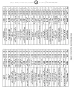
HeatStar HS4000 NG/LP Скачать руководство пользователя страница 13

NO.

HS#

BM2

 #

DESCRIPT

ION

NO.

HS#

BM2

 #

DESCRIPT

ION

01

50

345

G0

6139-9005

Ou

tlet cone

46

50

470

C30

376

Cab

le prot

ec

tio

n ø3

6m

m

02

50

346

M10203/1/B

Screw

 TE M6x1

0

47

50

260

E5

075

0

Sa

fety

 th

erm

ostat pla

stic prof

ile

03

50

347

G03

11

4

Flam

e gu

ard s

hield

48

50

370

G03

15

9-9010

Ba

se

04

50

348

G0

3147

Com

bust

ion c

ham

ber

49

50

077

P5

012

7

Contro

l b

ox 

cov

er

05

50

349

E5

0745

Sa

fety

 the

rm

ost

at TY

95

H

50

50

371

G0

028

6

El

ec

tri

ca

l c

om

ponen

ts

 d

ra

w

er 

co

m

pl

et

e

06

50

515

M20413

Clip holde

r sens

ing bu

lb

51

50

372

P5

013

2

Ele

ctrica

l com

po

nen

ts d

ra

w

er

07

50

351

G0

3150-9010

Upper body

52

50

093

E2

050

8

Fus

e holder

08

50

352

G0

3152-9010

Cover in

spe

ction

53

50

092

E1

031

3

Fus

e (

6x

30) 2

0A

09

50

353

G0

3154-9010

Lo

w

er bo

dy

54

50

373

E1

115

3

Relay

 fin

der 6

5.3

1.8.110

AC

10

50

411

C30372

Pro

tectio

n ca

ble ø35

55

50

374

E2

031

9

Term

ina

l boa

rd

11

50

354

G0

312

6

Com

bus

tion c

ha

m

ber de

fle

ct

ors

56

50

375

E2

030

5

Term

ina

l boa

rd

12

50

356

GA.0

10

0206

Elect

rod

e ionis

ation probe

57

50

329

E1

093

1

Transf

orm

er H.T. BRAHMA

13

50

545

I4

0332

Silicone p

ip

e ø5

x9

58

50

330

E4

022

9

C

on

tro

l bo

BR

AH

M

TG

RD

 81

 120

V

14

50

507

I3

9106

An

ti vibration jo

in

t

59

50

097

E1

112

5

Relay

 fin

de

r 6

5.3

1AC

15

50

500

I2

0326

Connec

tion 3/4"

FF

60

50

376

G06

073

Pla

te f

or ele

ctrica

l com

po

ne

nts

16

50

463

G06

23

9-9010

Motor f

lange

61

50

325

E2

041

8

Stop b

utto

n p

ro

tec

tio

n

17

50

469

C30374

Dra

in

 plug

62

50

337

E1

011

0-1-P

Sw

itch

 0-1

18

50

454

E1

0704-110

Motor 4

50 W

 w

/ capac

itor 8

F

63

50

570

E2

064

0

The

rm

os

ta

t plug

 3P+

T

19

50

455

E1

1249

Cap

ac

itor 80µ

F

64

50

011

E2

066

5

Dra

in

 plug

20

50

166

T10

261

Fan

 ø500

 23

°

65

50

009

E3

044

3

El

ec

tri

ca

l w

ire

 w

/p

lug

 and

 c

ab

le

 fa

st

ene

r

21

50

050

P3

0129

In

le

t g

rill

66

50

008

E1

103

0

La

m

p 12

0VAC

22

50

357

G06

33

0-9005

Va

lve support p

la

te

70

50

081

I2

032

5

Connec

tion

 1/8

"

23

50

506

I3

9102

Se

al 3/4

"

71

50

079

I3

113

0

Connec

tion

 s

traight ø6 1

/8"

24

50

505

I3

1205-1

Connec

tion 3/4

"MM

72

50

511

M103

23/1

Screw

 TCEI M4x2

0

25

50

500

I2

0326

Connec

tion 3/4

"FF

73

50

378

GA.001

020

8

Bu

rn

er plate

26

50

504

I3

1204

Connec

tion 3/4"

MM

74

50

379

GA.0

10

020

4

D

iff

us

ion

 ri

ng

 G

20

/G

25

-16

 ho

le

s ø

2.

6

27

50

358

T30

330-2

Ga

s sele

ctor valve

75

50

380

E2

067

9

Term

ina

l boa

rd

31

50

359

T30

333

Man

ual gas test f

iring va

lve

76

50

381

G0

312

9

Bu

rn

er s

up

port

32

50

360

E2

0943

Cable f

as

te

ne

r PG9

77

50

134

E1

021

5

Ig

nitio

n e

lec

trode

33

50

361

E2

0932

Nut f

or PG9

78

50

417

G02

07

8

H.T. cab

le

 con

nect

 90°

34

50

334

T30

111

Va

lve solenoid m

ain

79

50

382

G0

316

8-9005

Lif

tin

g f

ram

e

35

50

362

G0

6332-9005

Va

lv

e s

up

port

80

50

383

G03

16

9-9005

Lif

ting

 fram

e

36

50

516

M20907

Va

lv

e s

up

port

81

50

384

G0

317

0-9005

Bo

dy

 suppo

rt

37

50

363

G03

15

7-9010

Su

pport f

or pres

sure plate

82

50

385

G0

317

1-9005

W

he

el ax

le

 ø25

38

50

364

E5

0443

Pressu

re sw

itch

 33

0Pa

83

40

533

M201

11

W

asher ø26

 x

 ø44 x

 4m

m

39

50

365

I3

0414

Oil f

ilter

84

50

386

C10

556

W

he

el ø 2

60-ø 26

m

m

40

50

337

E5

0441

Pressu

re sw

itch

 20

0Pa

85

40

534

M205

05

W

he

el loc

king pin

41

50

366

I4

0336

Silicone p

ip

e ø4

x1.5

86

50

387

G0

317

2-9005

Su

ppo

rt

42

40

501

I4

0501

Silicone p

ip

e ø4

x8

87

50

388

G0

317

3-9005

Rignt f

ram

e

43

50

367

I2

0669

Conne

ctor straig

ht T ø4

88

50

389

G0

317

4-9005

Le

ft f

ram

e

44

50

368

E2

0952

Cable f

as

te

rn

er PG1

1

89

50

390

G0

317

5-9005

Han

dle

45

50

369

E2

0955

Nut f

or PG11

90

40

505

C10

203

Han

dle

HS4

000DF NG/LP HD Hea

ter Parts List BM2

13

ENERCO GROUP, INC. |Indirect Fired Portable Heater

Operating Instructions and Owner’s Manual

Содержание HS4000 NG/LP

Страница 1: ... 800 251 0001 DIRECT FIRED HEATER HEATSTAR BY ENERCO If the information in this manual is not followed exactly afire or explosion may result causing property damage personal injury or loss of life WARNING Do not store or use gasoline or other flammable vapors and liquids in the vicinity of this or any other appliance Service must be performed by a qualified service agency This is a vented portable...

Страница 2: ...AN INSTRUCTIONS MANUAL LABELS ETC CONTACT THE MANUFACTURER WARNING NOT FOR HOME OR RECREATIONAL VEHICLE USE WARNING YOUR SAFETY IS IMPORTANT TO YOU AND TO OTHERS SO PLEASE READ THESE INSTRUCTIONS BEFORE YOU OPERATE THIS HEATER The State of California requires the following warning CONTENTS WARNINGS 2 3 SPECIFICATIONS 4 OPERATION 5 SAFETY DEVICES 4 MAINTENANCE 5 VENTILATION 5 TROUBLESHOOTING 6 WIRI...

Страница 3: ...om the traffic building materials and contact with hot surfaces both during use andwhile in storage Proper gas supply must be provided to the inlet of the appliance Refer to rating plate for proper gas supply pressure Gas pressure in excess of maximum inlet pressure specified at the appliance inlet can cause fire or explosions leading to serious injury death building damage or loss of livestock Li...

Страница 4: ... 241 413 394 134 Manifold pressure in WC 4 28 4 50 Fuel consumption CFH 88 98 145 12 Altitude 2 000 4 500 ft above sea level Canada only Heat input BTU h 217 272 354 721 Manifold pressure in WC 4 06 4 27 Fuel consumption CFH 80 08 130 61 Air flow cfm 2 766 4 120 Power supply Phase 1 1 Voltage V 120 120 Frequency Hz 60 60 Electric consumption W 500 900 A 5 0 8 5 Ring nozzle in N 16 holes x 0 079 N ...

Страница 5: ...GNITION ELECTRODE 8 CONTROL FLAME ELECTRONIC RESET 9 HEATING SWITCH 10 ROOM THERMOSTAT PLUG 11 POWER CONTROL LAMP 12 POWER CORD 13 VENTILATION MODE SWITCH 14 PHASE NEUTRAL LINE TEST PUSH BUTTON MANIFOLD ASSEMBLY GE N 250 GE N 400 Fig 2 a GAS SELECTOR VALVE b MANIFOLD PRESSURE PORT MANIFOLD c MANIFOLD PRESSURE REGULATOR d MAIN GAS VALVE e INLET PRESSURE PORT f SHUT OFF FIRING VALVE 8 9 10 13 12 11 ...

Страница 6: ... air to function properly The air suction and or supply pipes are not blocked in any way there are not sheets or covers resting on the machine or walls and bulky objects near the heater The generator is placed near a power switchboard having specifications in conformity with those declared The unit is placed in a fixed position The generator is regularly monitored during operation and checked befo...

Страница 7: ...stallation in the U S A at elevation above 2 000 feet 610 m the appliance shall be derated 4 per cent for each 1 000 feet 305 m of elevation above sea level For installation in Canada at elevation above 2 000 feet to 4 500 feet above sea level the heater is deratedy reducing the input for the appropriate fuel in accordance with the rating plate manifold pressure THE CONVERSION SHALL BE CARRIED OUT...

Страница 8: ... cfr FAULTS CAUSES AND REMEDIES TRANSPORT AND HANDLING Before moving the unit Stop the machine as indicated in the STOP paragraph Disengage the power supply by removing the plug from the power socket Fully unscrew the fitting connecting the gas hose pipe to the heater Wait for the heater to cool down The hot air generators with wheels must be wheeled MAINTENANCE To regulate operation of the unit t...

Страница 9: ...d Make sure the fan is turning properly Check the electric motor and capacitor and if these are faulty replace The flame sensor is not operating correctly Remove the flame sensor and clean The safety thermostat trips due to overheating of the combustion chamber the thermostat electrical contact does not close during operation Makes sure the suction and feed grilles are not blocked Make sure the en...

Страница 10: ...DIAGRAM AP CONTROL BOX FU FUSE EL IONIZATION ELECTRODE FUA FUSE LI POVERHEAT THEMOSTAT PA PRESSURE SWITCH 20 Pa TA ROOM THERMOSTAT PLUG IT TRANSFORMER H T CO CAPACITOR RV HEATING SWITCH RE MOTOR RELAY ST CONTROL LAMP EV GAS TRAIN MV COOLING MOTOR RV1 VENTILATION MODE SWITCH RE1 POST VENTILATION RELAY ...

Страница 11: ...0 49 22 B 36 62 63 64 66 65 51 52 53 55 56 58 60 57 61 48 HS4000NG LP 23 24 25 26 27 26 35 32 34 33 42 71 70 C 62 59 54 38 44 45 37 41 42 39 05 47 46 10 01 03 02 04 09 40 43 26 31 A 50 C B 11 ENERCO GROUP INC Indirect Fired Portable Heater Operating Instructions andOwner s Manual ...

Страница 12: ...PL 10 07 80 88 90 87 86 82 83 84 81 81 79 89 HS4000NG LP 85 12 ENERCO GROUP INC Indirect Fired Portable Heater Operating Instructions andOwner s Manual ...

Страница 13: ...3 Electrical wire w plug and cable fastener 21 50050 P30129 Inlet grill 66 50008 E11030 Lamp 120VAC 22 50357 G06330 9005 Valve support plate 70 50081 I20325 Connection 1 8 23 50506 I39102 Seal 3 4 71 50079 I31130 Connection straight ø6 1 8 24 50505 I31205 1 Connection 3 4 MM 72 50511 M10323 1 Screw TCEI M4x20 25 50500 I20326 Connection 3 4 FF 73 50378 GA 0010208 Burner plate 26 50504 I31204 Connec...

Страница 14: ...ns in material or workmanship If a part is damaged or missing call our Technical Support Department at 800 251 0001 Address any Warranty Claims to the Service Department Enerco Group Inc 4560 W 160TH ST Cleveland Ohio 44135 Include your name address and telephone number and include details concerning the claim Also supply us with the purchase date and the name and address of the dealer from whom y...

Страница 15: ... matériel ou de main d œuvre Si une pièce est endommagée ou manquante téléphonez à notre service de soutien technique au 800 251 0001 Adressez toute réclamation relative à la garantie à Service Department Enerco Group Inc 4560 W 160TH ST Cleveland Ohio 44135 États Unis Indiquez vos nom adresse et numéro de téléphone ainsi que les détails de la réclamation Indiquez nous également la date d achat et...

Страница 16: ...ug 3P T 19 50455 E11249 Capacitor 80µF 64 50011 E20665 Drain plug 20 50166 T10261 Fan ø500 23 65 50009 E30443 Electrical wire w plug and cable fastener 21 50050 P30129 Inlet grill 66 50008 E11030 Lamp 120VAC 22 50357 G06330 9005 Valve support plate 70 50081 I20325 Connection 1 8 23 50506 I39102 Seal 3 4 71 50079 I31130 Connection straight ø6 1 8 24 50505 I31205 1 Connection 3 4 MM 72 50511 M10323 ...

Страница 17: ...12 PL 10 07 80 88 90 87 86 82 83 84 81 81 79 89 HS4000NG LP 85 ...

Страница 18: ...5 16 20 17 19 21 77 76 74 72 73 A 08 18 78 13 50 49 22 B 36 62 63 64 66 65 51 52 53 55 56 58 60 57 61 48 HS4000NG LP 23 24 25 26 27 26 35 32 34 33 42 71 70 C 62 59 54 38 44 45 37 41 42 39 05 47 46 10 01 03 02 04 09 40 43 26 31 A 50 C B ...

Страница 19: ...RODE D IONISATION FUA FUSIBLE LI THERMOSTAT PUISSANCE CHAUFFAGE PA PRESSOSTAT 20 Pa RE2 RELAIS RETARD DÉMARRAGE opt TA PRISE THERMOSTAT D AMBIANCE IT TRANSFORMATEUR H T CO CONDENSATEUR RV INTERRUPTEUR DE CHAUFFAGE RE RELAIS MOTEUR ST VOYANT DE CONTRÔLE EV CONDUIT GAZ MV REFROIDISSEMENT MOTEUR RV1 INTERRUPTEUR MODE VENTILATION RE1 RELAIS POST VENTILATION R RÉSISTANCE ANTI HUMIDITÉ opt ...

Страница 20: ...du pressostat d air suite au dysfonctionnement du ventilateur Vérifier que les grilles de l aspiration et de l évacuation ne sont pas obstruées Vérifier que le ventilateur tourne librement Vérifier le moteur électrique et le condensateur et les remplacer s ils sont défectueux Le capteur de flamme ne fonctionne pas correctement Retirer le capteur de flamme et le nettoyer le contact électrique du th...

Страница 21: ...g 1 2 VENTILATION Pour obtenir la fonction ventilation uniquement contrôler que l interrupteur 9 est sur 0 et placer l interrupteur 14 sur la position 1 Pour l arrêter placer l interrupteur 14 sur la position 0 Attention Quel que soit la raison l unité essaiera de redémarrer une fois Si la cause du dysfonctionnement continue le générateur s arrêtera définitivement et la voyant 8 s allumera Le géné...

Страница 22: ...MISE EN MARCHE Le générateur PHOEN N est fourni après un test de fonctionnement complet et il est donc prédisposé pour l un des gaz naturel ou GPL indiqué dans le Tab I L étiquette adhésive collée sur la soupape de sélection du gaz 13 indique la catégorie de fonctionnement de l appareil généralement gaz naturel Si l alimentation se fait avec un autre type de gaz de gaz naturel à GPL et inversement...

Страница 23: ... de 6 m 20 pieds d une cuve de gaz propane et à moins de 3 mètres 10 pieds d une bouteille de gaz Le générateur ne doit pas être installé dans des zones à fort risque d incendie ou d explosion Toutes les mesures aptes à prévenir les incendies devront être adoptées Pour la distribution d air à partir du distributeur utiliser uniquement des conduits d origine de type M1 Spiraflex et respecter la lon...

Страница 24: ...CTRODE 8 RAZ ÉLECTRONIQUE CONTRÔLE FLAMME 9 INTERRUPTEUR DE CHAUFFAGE 10 PRISE THERMOSTAT D AMBIANCE 11 VOYANT DE MISE SOUS TENSION 12 CORDON D ALIMENTATION 13 INTERRUPTEUR MODE VENTILATION 14 POUSSOIR TEST LIGNE PHASE NEUTRE ENSEMBLE COLLECTEUR GE N 250 GE N 400 Fig 2 a VALVE SÉLECTEUR GAZ b PORT PRESSION COLLECTEUR COLLECTEUR c RÉGULATEUR PRESSION COLLECTEUR d SOUPAPE PRINCIPALE GAZ e PORT PRESS...

Страница 25: ...alve position Normal altitude 0 2 000 ft above sea level U S A and Canada Puissance thermique à l entrée BTU h 241 413 394 134 Manifold pressure in WC 4 28 4 50 Fuel consumption CFH 88 98 145 12 Altitude 2 000 4 500 ft above sea level Canada only Puissance thermique à l entrée BTU h 217 272 354 721 Manifold pressure in WC 4 06 4 27 Consommation CFH 80 08 130 61 Débit d air cfm 2 766 4 120 Alimenta...

Страница 26: ...rrosion pouvant provoquer des fuites de gaz et entraîner des d incendies ou des explosions L assemblage du tuyau flexible doit être protégé de la circulation des matériaux de construction et de tout contact avec des surfaces chaudes tant pendant l utilisation que pendant l entreposage ATTENTION Le générateur doit être branché à un circuit d alimentation de gaz dont les caractéristiques sont approp...

Страница 27: ...L D INSTRUCTIONS ÉTIQU ETTES ETC V EUILLEZ COMMUNIQU ER AV EC LE FABRICANT AVERTISSEMENT NON CONÇU POUR UNE UTILISATION DANS LA MAIS ON OU UN VÉHICUL E RÉCRÉATIF AVERTISSEMENT VOTRE SÉCURITÉ PERSONNELLE ÉTANT IMP ORTANTE POUR TOUS VEUILLEZ LIRE LES INSTRUCTIONS AVANT D UTILISER CET APPAREIL DE CHAUFFAGE L État de la Californie exige que l avertissement suivant soit fourni AVERTISSEMENT LISEZ LES I...

Страница 28: ...tre appareil Le service doit être exécuté par une agence de service qualifiée C est un chauffage portatif déchargé L air de combustion adéquat et la ventilation doivent être fournis Faites allusion à la page 5 MODÈLE LISEZ SOIGNEUSEMENT LES INSTRUCTIONS Lisez et observez toutes les instructions Conservez les instructions pour vous y référer ultérieurement Interdisez à quiconque n ayant pas lu les ...

Отзывы: