background image

Heat & Glo  •  6000C-IPI, 8000C-IPI  •  2164-900 Rev. W  •  8/14

2

Listing Label Information/Location

Model Name: ___________________________________________ Date purchased/installed: __________________

Serial Number: __________________________________________ Location on 

fi

 replace: _____________________

Dealership purchased from:  _______________________________ Dealer Phone:  __________________________

Notes: _______________________________________________________________________________________

_____________________________________________________________________________________________

A. Congratulations

Congratulations on selecting a Heat & Glo gas 

fi

 replace, an 

elegant and clean alternative to wood burning 

fi

 replaces. 

The Heat & Glo gas 

fi

 replace you have selected is designed 

to provide the utmost in safety, reliability, and ef

fi

 ciency.

As the owner of a new 

fi

 replace, you’ll want to read and 

carefully follow all of the instructions contained in this 
owner’s manual. Pay special attention to all cautions and 
warnings.

This owner’s manual


should be retained for future 

reference. We suggest that you keep it with your other 
important documents and product manuals.
The information contained in this owner’s manual, unless 
noted otherwise, applies to all models and gas control 
systems.
Your new Heat & Glo gas 

fi

 replace will give you years of 

durable use and trouble-free enjoyment. Welcome to the 
Heat & Glo family of 

fi

 replace products!

We recommend that you record the following pertinent 
information about your 

fi

 replace.

The model information regarding your speci

fi

 c 

fi

 replace can be found on 

the rating plate usually located in the control area of the 

fi

 replace.

Homeowner Reference Information

Read this manual before installing or operating this appliance. 

Please retain this owner’s manual for future reference.

Gas and Electric 
Information

Serial Number

Type of Gas

Model Number

Not 

Not for 

for use 

use with 

with solid 

solid fuel.

fuel.

((

Ne 

Ne doit 

doit pas 

pas entre 

entre utilise 

utilise avec 

avec un 

un combustible 

combustible solide).

solide).

This 

This appliance 

appliance must 

must be 

be installed 

installed in 

in accordance 

accordance with 

with local 

local codes, 

codes, if 

if any; 

any; if 

if not, 

not, follow 

follow ANSI 

ANSI Z223.1

Z223.1

in 

in the 

the USA 

USA or 

or CAN/CGA 

CAN/CGA B149 

B149 installation 

installation codes. 

codes. 

(Installer 

(Installer l’appareil 

l’appareil selon 

selon les 

les codes 

codes ou 

ou reglements

reglements

locaux 

locaux ou, 

ou, en 

en l’absence 

l’absence de 

de tels 

tels reglements, 

reglements, selon 

selon les 

les codes 

codes d’installation 

d’installation CAN/CGA-B149.)

CAN/CGA-B149.)

Type 

Type of 

of Gas 

Gas 

(Sorte 

(Sorte De 

De Gaz)

Gaz)

::

N

NA

ATURAL

TURAL  GAS

GAS

MADE 

MADE   IN 

IN   USA

USA

Minimum 

Minimum Permissible 

Permissible Gas 

Gas Supply 

Supply for 

for Purposes 

Purposes of 

of Input 

Input Adjustment.

Adjustment.

Approved 

Approved Minimum 

Minimum 

(De 

(De Gaz) 

Gaz) 

Acceptable

Acceptable 0.0

0.0  in 

in w.c.

w.c.

(Po. 

(Po. Col. 

Col. d’eau)

d’eau)

Maximum 

Maximum Pressure 

Pressure 

(Pression)

(Pression)

  0.0

0.0  in 

in w.c.

w.c.

(Po. 

(Po. Col. 

Col. d’eau)

d’eau)

Maximum 

Maximum Manifold 

Manifold Pressure 

Pressure 

(Pression)

(Pression)


   0.0

0.0  in 

in w.c.

w.c.

(Po. 

(Po. Col. 

Col. d’eau)

d’eau)

Minimum 

Minimum Manifold 

Manifold Pressure 

Pressure 

(Pression)

(Pression)


   0.0

0.0  in 

in w.c.

w.c.

(Po. 

(Po. Col. 

Col. d’eau)

d’eau)

Model:

Model:

(Modele):

(Modele):

Serial

Serial

(Serie):

(Serie):

ANSI 

ANSI Z21XX-XXXX 

Z21XX-XXXX · 

· CSA 

CSA 2.XX-MXX 

2.XX-MXX  

XXXXXXXX

XXXXXXXX

IN 

IN CANADA

CANADA

ALTITUDE:

ALTITUDE:

0-0000 

0-0000 FT.

FT.

0000-0000FT.

0000-0000FT.

MAX. 

MAX. INPUT 

INPUT BTUH:

BTUH:

00,000

00,000

00,000

00,000

MIN. 

MIN. INPUT 

INPUT BTUH:

BTUH:

00,000

00,000

00,000

00,000

ORIFICE 

ORIFICE SIZE:

SIZE:

#XXXXX

#XXXXX

#XXXXX

#XXXXX

XXXXXXXX

XXXXXXXX

Total 

Total Electrical 

Electrical Requirements: 

Requirements: 000Vac, 

000Vac, 00Hz., 

00Hz., less 

less than 

than 00 

00 Amperes

Amperes


Heat & Glo, a brand of Hearth & Home Technologies
7571 215th Street West, Lakeville, MN   55044

Содержание 6000C-IPI

Страница 1: ...ration DO NOT DISCARD Important operating and maintenance instructions included Read understand and follow these instructions for safe installation and operation In the Commonwealth of Massachusetts installation must be performed by a licensed plumber or gas fitter See Table of Contents for location of additional Commonwealth of Massachusetts requirements WARNING A barrier designed to reduce the r...

Страница 2: ...Type of Gas Model Number Not Not for for use use with with solid solid fuel fuel Ne Ne doit doit pas pas entre entre utilise utilise avec avec un un combustible combustible solide solide This This appliance appliance must must be be installed installed in in accordance accordance with with local local codes codes if if any any if if not not follow follow ANSI ANSI Z223 1 Z223 1 in in the the USA U...

Страница 3: ...Design and Installation Considerations 20 C Tools and Supplies Needed 20 D Inspect Appliance and Components 20 5 Framing and Clearances A Selecting Appliance Location 21 B Constructing the Appliance Chase 22 C Clearances 22 D Mantel and Wall Projections 23 6 Termination Locations A Vent Termination Minimum Clearances 24 7 Vent Information and Diagrams A Approved Pipe 26 B Vent Table Key 26 C Use o...

Страница 4: ...ly 60 B Remove the Shipping Materials 60 C Clean the Appliance 60 D Accessories 60 E Burner Top Installation 60 F Ember Placement 60 G Install the Log Assembly 61 H Fixed Glass Assembly 65 I Install Trim and or Surround 65 J Air Shutter Setting 65 15 Troubleshooting A IntelliFire Plus Ignition System 66 16 Reference Materials A Appliance Dimension Diagram 68 B Vent Components Diagrams 70 C Service...

Страница 5: ...purchase In the case of new home construction warranty coverage begins on the date of first occupancy of the dwelling or six months after the sale of the product by an independent authorized HHT dealer distributor whichever occurs earlier The warranty shall commence no later than 24 months following the date of product shipment from HHT regardless of the installation or occupancy date The warranty...

Страница 6: ...ECIFIED ABOVE WARRANTY EXCLUSIONS This warranty does not cover the following Changes in surface finishes as a result of normal use As a heating appliance some changes in color of interior and exterior surface finishes may occur This is not a flaw and is not covered under warranty Damage to printed plated or enameled surfaces caused by fingerprints accidents misuse scratches melted items or other e...

Страница 7: ... Appliances for Manufactured Homes and Recreational Vehicles and Gas Fired Appliances for Use at High Altitudes A Appliance Certification NOT INTENDED FOR USE AS A PRIMARY HEAT SOURCE This appliance is tested and approved as either supplemen tal room heat or as a decorative appliance It should not be factored as primary heat in residential heating calculations D High Altitude Installations NOTICE ...

Страница 8: ...aterials made of or surfaced with wood compressed pa per plant fibers plastics or other material that can ignite and burn whether flame proofed or not or plastered or unplastered shall be considered combustible materials G Electrical Codes NOTICE This appliance must be electrically wired and grounded in accordance with local codes or in the absence of local codes with National Electric Code ANSI N...

Страница 9: ...ed heating appliance or equipment The sign shall read in print size no less than one half 1 2 in in size GAS VENT DIRECTLY BELOW KEEP CLEAR OF ALL OB STRUCTIONS Inspection The state or local gas inspector of the side wall horizon tally vented gas fueled equipment shall not approve the installation unless upon inspection the inspector ob serves carbon monoxide detectors and signage installed in acc...

Страница 10: ...oling down Teach children to NEVER touch the fireplace WARNING A barrier designed to reduce the risk of burns from the hot viewing glass is provided with this appliance and shall be installed DO NOT operate the appliance with the barrier removed If the barrier becomes damaged the barrier shall be replaced with the manufacturer s barrier for this appliance Contact your dealer or Hearth Home Technol...

Страница 11: ...Unapproved doors or fronts may cause fireplace to overheat This fireplace has been supplied with an integral barrier to prevent direct contact with the fixed glass panel DO NOT operate the fireplace with the barrier removed Contact your dealer or Hearth Home Technologies if the barrier is not present or help is needed to properly install one For more information refer to the instructions supplied ...

Страница 12: ...nitial 10 seconds of operation If the HI LO is switched to the LO position the flame output will automatically drop to the lowest setting after the flame has been established for 10 sec After this 10 second period the flame can be adjusted from HI to LO with the switch 3 Thecontrolmodulehassafetyfeaturethatautomatically shuts down the fireplace after 9 hours of continuous operation without receivi...

Страница 13: ...O IF YOU SMELL GAS DO NOT try to light any appliance DO NOT touch any electric switch do not use any phone in your building DO NOT CONNECT LINE VOLT AGE 110 120 VAC OR 220 240 VAC TO THE CONTROL VALVE Improper installation adjustment al teration service or maintenance can cause injury or property damage Re fer to the owner s information manual provided with this appliance This appliance needs fres...

Страница 14: ... to burn for 20 to 40 minutes Odor from appliance When first operated this appliance may release an odor for the first several hours This is caused by the curing of the paint and the burning off of any oils remaining from manufacturing Odor may also be released from finishing materials and adhesives used around the appliance Film on the glass This is a normal result of the curing process of the pa...

Страница 15: ...m carpeting or other factors Control compartment burner and circulating air passageway of the fireplace must be kept clean CAUTION Risk of Burns The fireplace should be turned off and cooled before servicing When properly maintained your fireplace will give you many years of trouble free service We recommend an nual service by a qualified service technician Doors Surrounds Fronts Frequency Annuall...

Страница 16: ...ace if firebox has been perforated Control Compartment and Firebox Top Frequency Annually By Qualified Service Technician Tools needed Protective gloves vacuum cleaner dust cloths Vacuum and wipe out dust cobwebs debris or pet hair Use caution when cleaning these areas Screw tips that have penetrated the sheet metal are sharp and should be avoided Remove all foreign objects Verify unobstructed air...

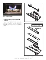
Страница 17: ... necessary to remove the refractory grate and valve assemblies This task should be performed by a qualified service technician The grate and base refrac tory do not need to be removed to service the burner assembly Figure 3 2 Grate Removal Note The base refractory must be removed to access screws Figure 3 4 Base Refractory Removal BASE REFRACTORY ...

Страница 18: ...sed for identification and verification purposes This task should be performed by a qualified ser vice technician The base refractory valve plate and grate do not need to be removed to access the burner assembly The logs and fiber burner top need to be removed to access the burner Disconnect the pilot from the burner before removal See Figure 3 5 for burner identification chart Notch patterns are ...

Страница 19: ...RAFTERS SECTION 8 C FRAMING HEADED OFF IN CEILING JOISTS SECTION 8 C GAS LINE SECTION 11 MANTEL AND MANTEL LEG SECTION 5 D SURROUND HEARTH EXTENSION VENT PIPE SECTIONS 7 and 8 OPTIONAL WALL SWITCH STORM COLLAR SECTION 10 H NON COMBUSTIBLE ROOF FLASHING MAINTAINS MINIMUM CLEARANCE AROUND PIPE SECTION 10 G FRAMING HEADER SECTION 5 B ATTIC INSULATION SHIELD NOT SHOWN MUST BE USED HERE TO KEEP INSULAT...

Страница 20: ...sion Damaged parts could impair safe operation DO NOT install damaged in complete or substitute components Keep appliance dry C Tools and Supplies Needed Before beginning the installation be sure that the following tools and building supplies are available Tape measure Framing material Pliers Non corrosive leak check solution Hammer Phillips screwdriver Gloves Framing square Voltmeter Electric dri...

Страница 21: ... typical installations and are FOR DESIGN PURPOSES ONLY Illustrations diagrams are not drawn to scale Actual installation may vary due to individual design preference Figure 5 1 Appliance Locations 6000 Models 1 2 IN REAR VENT HORIZONTAL TERMINATION TWO ELBOWS REAR VENT NO ELBOWS REAR VENT ONE ELBOW ALCOVE INSTALLATION TOP VENT ONE 90º ELBOW A B C B E B B B D D F G H D A D NOTE THE REAR STANDOFF M...

Страница 22: ...aces extending full width and depth DO NOT install directly on carpeting vinyl tile or any combustible material other than wood WARNING Risk of Fire Maintain specified air space clearances to appliance and vent pipe Insulation and other materials must be secured to prevent accidental contact The chase must be properly blocked to prevent blown insulation or other combustibles from entering and maki...

Страница 23: ...5 18 A B INTERIOR WALL TOP VIEW MANTEL LEG OR WALL PROJECTIONS FIREPLACE OPENING Note All measurements in inches If A minimum is ____ then B maximum is_____ A Inches 2 7 16 3 7 16 4 7 16 5 7 16 6 7 16 7 7 16 Millimeters 62 87 113 138 164 189 B Inches 1 2 3 4 5 Millimeters 25 51 76 102 127 Note Measurement is taken from top of the opening NOT the top of the fireplace Figure 5 4 Clearances to Mantel...

Страница 24: ...ES MIN H MIN MINIMUM HEIGHT FROM ROOF TO LOWEST DISCHARGE OPENING 6 6 Termination Locations Fire Risk Maintain vent clearance to combustibles as specified DO NOT pack air space with insulation or other materials Failure to keep insulation or other materials away from vent pipe may cause overheating and fire WARNING Gas Wood or Fuel Oil Termination Cap B Gas Termination Cap A If using decorative ca...

Страница 25: ...V V H Electrical Service V K V K V L C V N 6 inches non vinyl sidewalls 12 inches vinyl sidewalls O 18 inches non vinyl soffit and overhang 42 inches vinyl soffit and overhang P 8 ft QMIN RMAX 1 cap 3 feet 2 x Q ACTUAL 2 caps 6 feet 1 x Q ACTUAL 3 caps 9 feet 2 3 x Q ACTUAL 4 caps 12 feet 1 2 x Q ACTUAL QMIN termination caps x 3 RMAX 2 termination caps x QACTUAL Covered Alcove Applications Spaces ...

Страница 26: ... A length of straight pipe is allowed between two 45º elbows see Figure 7 1 Figure 7 1 7 7 Vent Information and Diagrams B Vent Table Key The abbreviations listed in this vent table key are used in the vent diagrams D Measuring Standards Vertical and horizontal measurements listed in the vent diagrams were made using the following standards Pipe measurements are shown using the effective length of...

Страница 27: ...ling first elbow WARNING WARNING E Vent Diagrams Note The 6000 8000 series fireplaces can adapt to SLP series vent pipe if desired When venting off the top of the unit use a DVP 2SL adapter and a minimum 48 inch vertical section of SLP series vent pipe A DVP SLP24 adapter may also be used with a 24 inch vertical section of SLP series vent pipe After the 48 inch vertical section the venting table r...

Страница 28: ...pipe to clear the top standoffs 6000C IPI V1 Minimum H1 H2 Maximum Elbow only Not allowed 6 in 152 mm 2 ft 610 mm 1 ft 305 mm 4 ft 1 2 m 1 1 2 ft 457 mm 11 ft 3 4 m 2 ft 610 mm 19 ft 3 8 m 2 1 2 ft 762 mm 22 ft 6 7 m V1 H1 H2 40 ft 12 2 m Maximum H1 H2 22 ft 6 7 m Maximum V1 1 ft 305 mm Minimum 8000C IPI V1 Minimum H1 H2 Maximum Elbow only Not allowed 6 in 152 mm Not allowed 1 ft 305 mm 2 ft 610 m...

Страница 29: ... ap pliance the flue restrictor should be used V1 V1 40 ft Max 12 4 m V1 3 ft Min 914 mm Flue Restrictor Instructions 1 Remove exhaust shield using a 1 4 inch nut driver by removing the four screws securing it in place see Figure 7 7 Figure 7 8 Flue Restrictor 2 Break the flue restrictor into two pieces Do this by bending the part back and forth until it breaks see Figure 7 8 Figure 7 7 BREAK HERE...

Страница 30: ...NG LP NG LP 4 ft 1 1 No Restrictor No Restrictor No Restrictor 8 ft 2 2 1 2 1 1 No Restrictor 15 ft 3 3 3 2 2 2 1 2 20 ft 3 4 3 3 3 3 2 3 25 ft 3 4 3 3 3 3 2 3 30 ft 4 4 3 4 3 4 3 3 35 ft 4 4 3 4 3 4 3 3 40 ft 4 4 4 4 4 4 3 4 V1 H1 Maximum V2 V1 V2 Min Elbow only 2 ft 610 mm 6 in 152 mm 6 ft 1 8 m 2 ft 610 mm 11 ft 3 4 m 3 ft 914 mm 16 ft 4 9 m 4 ft 1 2 m 20 ft 6 1 m V1 V2 H1 50 ft 15 2 m Maximum ...

Страница 31: ...nimum H1 H2 Maximum Elbow only 1 ft 305 mm 1 ft 305 mm 6 in 152 mm 2 ft 610 mm 2 ft 610 mm 1 ft 305 mm 2 ft 610 mm 2 ft 610 mm 2 ft 610 mm 4 ft 1 2 m 4 ft 1 2 m 3 ft 914 mm 9 ft 2 7 m 9 ft 2 7 m 4 ft 1 2 m 18 ft 5 5 m 18 ft 5 5 m H1 H2 20 ft 6 1 m Maximum V1 V2 H1 H2 40 ft 12 2 m Maximum No specific restrictions on this value EXCEPT V1 V2 H1 H2 cannot exceed 40 ft 12 2 m ...

Страница 32: ...I 8000C IPI 2164 900 Rev W 8 14 32 H1 Rear Vent Horizontal Termination Figure 7 14 No Elbow One 45º Elbow H1 H1 16 in 406 mm Maximum Do not use a 45º elbow in corner installations Use two 90º elbows instead Figure 7 13 ...

Страница 33: ... 2 m 7 ft 2 1 m 3 ft 914 mm 3 ft 914 mm 9 ft 2 7 m 12 ft 3 7 m 3 ft 914 mm 4 ft 1 2 m 17 ft 5 2 m 20 ft 6 1 m V1 H1 H2 40 ft 12 2 m Maximum H1 3 ft 914 mm Maximum H1 H2 20 ft 6 1 m Maximum H1 Maximum V1 Minimum H2 H3 H1 H2 H3 Max 1 ft 305 mm Back to Back 90º Elbows 1 ft 305 mm 2 ft 610 mm 2 ft 610 mm 6 in 152 mm 1 5 ft 457 mm 3 5 ft 1 1 m 3 ft 914 mm 1 ft 305 mm 2 ft 610 mm 5 ft 1 5 m 3 ft 914 mm ...

Страница 34: ...in 152 mm 2 ft 610 mm 1 ft 305 mm 3 ft 914 mm 2 ft 610 mm 5 ft 1 5 m 3 ft 914 mm 7 ft 2 1 m 4 ft 1 2 m 8 ft 2 4 m 5 ft 1 5 m 8 ft 2 4 m V1 H1 40 ft 12 2 m Maximum H1 8 ft 2 4 m Maximum V1 Minimum H1 H2 Maximum Back to Back 90º Elbows 3 ft 914 mm 2 ft 610 mm 6 ft 1 8 m 4 ft 1 2 m 9 ft 2 7 m 6 ft 1 8 m 12 ft 3 7 m 8 ft 2 4 m 15 ft 4 6 m V1 H1 H2 40 ft 12 2 m Maximum H1 H2 15 ft 4 6 m Maximum ...

Страница 35: ...m 8 ft 2 4 m V1 H1 H2 H3 40 ft 12 2 m Maximum No specific restrictions on this value EXCEPT V1 H1 H2 H3 cannot exceed 40 ft 12 2 m Maximum H1 H2 H3 8 ft 2 4 m Maximum H1 Maximum V1 Minimum H2 H1 H2 Maximum 2 ft 610 mm 6 in 152 mm 2 ft 610 mm 4 ft 1 2 m 3 ft 914 mm 1 ft 305 mm 4 ft 1 2 m 7 ft 2 1 m 5 ft 1 5 m 2 ft 610 mm 6 ft 1 8 m 11 ft 3 4 m 7 ft 2 1 m 3 ft 914 mm 8 ft 2 4 m 15 ft 4 6 m 8 ft 2 4 ...

Страница 36: ...NG Risk of Fire Coaxial to colinear venting configuration may only be used in existing non combus tible chimney Installation in any other venting application could cause fire Prior to installing the gas appliance Have the chimney and adjacent structure inspected and cleaned by qualified professionals Hearth Home Technologies recommends that NFI or CSIA certified professionals or technicians under ...

Страница 37: ...P 2SL kit Attach the DV 46DVA GCL adapter to the appliance starting collar with 3 1 2 in self tapping screws See Figure 7 23 Rear Vent Remove the rear seal cap and insulation if equipped Connect the DVP 2SL adapter to the vertically positioned elbow Follow installation instructions included with DVP 2SLkit Secure DV 46DVA GCLadapter to DVP 2SLwith 3 1 2 in self tapping screws See Figure 7 23 Conne...

Страница 38: ...If your local inspector requires a wall shield firestop on both sides then both wall shield firestops must have a heat shield refer to Section 16 B attached to them See Section 10 M for information for regarding the in stallation of a horizontal termination cap Non Combustible Wall Penetration If the hole being penetrated is surrounded by noncom bustible materials such as concrete a hole with diam...

Страница 39: ...Insulation must be kept back from the pipe to prevent overheating Figure 8 3 Installing Ceiling Firestop Figure 8 4 Installing the Attic Shield INSTALL ATTIC INSULATION SHIELDS BEFORE OR AFTER INSTALLATION OF VENT SYSTEM CEILING FIRESTOP INSTALLED BELOW CEILING CEILING FIRESTOP INSTALLED ABOVE CEILING ATTIC ABOVE A PIPE DVP SLP A 10 in 254 mm 9 in 229 mm A D Install Attic Insulation Shield WARNING...

Страница 40: ... fireplace and discard it See Figure 8 5 Center the duct collar around the exposed hole and attach it to the fireplace with 3 screws Note Do this BEFORE final positioning of fireplace Determine the location for the air register fan housing assembly Reference the Heat Zone Gas kit instructions for the remaining installation steps HEAT ZONE GAS ATTACHES HERE ...

Страница 41: ...he rectangles next to the disk For rear vent skip this step Figure 9 2 Remove the white gasket material covering the seal cap Figure 9 4 Remove the insulation basket and white insu lation from the center vent pipe Figure 9 5 Remove the insulation from the outer vent pipe For rear venting there is no insulation in the outer vent pipe NOTICE Once the seal cap has been removed it CANNOT be reattached...

Страница 42: ...ing band out and use to remove the seal cap Figure 9 10 Discard the vent cap remove and discard the insulation basket NOTICE Once the seal cap has been removed it CANNOT be reattached Figure 9 6 To attach the first section of vent pipe make sure to use the fiberglass gasket in the manual bag to seal between the first vent component and the outer fireplace wrap Use 2 self tapping screws to secure t...

Страница 43: ...Make sure insulation and other materials are secured DO NOT notch the framing around the appliance standoffs Failure to maintain air space clearance may cause overheating and fire The diagram shows how to properly position and secure the appliance see Figure 9 15 Nailing tabs are provided to secure the appliance to the framing members Bend out nailing tabs on each side Place the appliance into pos...

Страница 44: ...O NOT penetrate inner pipe For 90º and 45º elbows that are changing the vent direction from horizontal to vertical one screw minimum should be put in the outer flue at the horizontal elbow joint to prevent the elbow from rotating Use screws no longer than 1 2 in 13 mm If predrilling screw holes DO NOT penetrate inner pipe Commercial Multi family Multi level exceeding two sto ries or High Rise Appl...

Страница 45: ...ealed All unit collar pipe slip section elbow and cap outer flues shall be sealed in this manner unless otherwise stated Figure 10 5 Adding Venting Components WARNING Risk of Fire or Explosion DO NOT break silicone seals on slip sections Use care when remov ing termination cap from slip pipe If slip section seals are broken during removal of the termination cap vent may leak Note Align seams to en...

Страница 46: ...y 8 ft 2 44 m after the maximum allowed 25 ft 7 62 m of unsupported rise Vertical runs originating off the rear of the appliance or after any elbow must be supported every 8 ft 2 44 m Horizontal runs must be supported every 5 feet 1 52 m Vent supports or plumbers strap spaced 120º apart may be used to support vent sections See Figures 10 8 and 10 9 Wall shield firestops may be used to provide hori...

Страница 47: ...l ceiling support box on the outside roof Remove shingles or other roof covering as necessary to cut the rectangular hole for the support box Cut the hole 1 8 in 3 mm larger than the support box outline Lower the support box through the hole in the roof until its bottom is at least 2 in 51 mm below the ceiling Figure 10 12 Level the support box both vertically and horizontally and temporarily tack...

Страница 48: ...ISCHARGE OPENING Figure 10 16 Assembling the Storm Collar Around the Pipe Figure 10 16 Assembling the Storm Collar Around the Pipe NOTICE Failure to properly caulk the roof flashing and pipe seams may permit entry of water Caulk the gap between the roof flashing and the outside diameter of the pipe Caulk the perimeter of the flashing where it contacts the roof surface See Figure 10 15 Caulk the ov...

Страница 49: ...G Risk of Fire To prevent overheating and fire heat shields must extend through the entire wall thick ness DO NOT remove the heat shields attached to the wall shield firestop and the horizontal termination cap shown in Figure 10 19 Heat shields must overlap 1 1 2 in 38 mm mini mum There are two sections of the heat shield One section is factory attached to the wall shield firestop The other sectio...

Страница 50: ... When installing a horizontal termination cap follow the cap location guidelines as prescribed by current ANSI Z223 1 and CAN CGA B149 installation codes and refer to Section 6 of this manual CAUTION Risk of Burns Local codes may require in stallation of a cap shield to prevent anything or anyone from touching the hot cap NOTICE For certain exposures which require superior resistance to wind drive...

Страница 51: ...ution DO NOT use open flame Fittings and connections could have loos ened during shipping and handling WARNING Risk of Fire DO NOT change valve settings This valve has been preset at the factory WARNING Risk of Fire or Explosion High pressure will damage valve Low pressure may cause explosion Verify inlet pressures Verify minimum pressures when other household gas appliances are operating Install ...

Страница 52: ...or Explosion DO NOT wire 110V to the valve or to the appliance wall switch Incorrect wiring will damage controls Determine if the appliance uses an IntelliFire Plus igni tion system or standing pilot ignition system Open the control access panel or remove the decorative front A red or black ignitor button as shown in Figure 12 1 indicates this appliance is standing pilot ignition B IntelliFire Plu...

Страница 53: ... 2 IPI Wiring Diagram TO JUNCTION BOX 110V MODULE FLAME SENSE IGNITER RC100 RC200 OPTIONAL WALL CONTROLS GROUND ORANGE PILOT GREEN MAIN BROWN BATTERY PACK 6V DC FLAME MODULATION THERMOSTAT WIRE ASSEMBLY WALL SWITCH WIRE BLACK BLACK BLACK RED RED BLACK I S ORG WHT ...

Страница 54: ...Switch or BC10 E Junction Box Installation If the box is being wired from the INSIDE of the appliance Remove the screw attaching the junction box receptacle to the outer shell rotate the junction box inward to disengage it from the outer shell see Figure 12 3 Pull the electrical wires from outside the appliance through the opening into the valve compartment and secure wires with a Romex connector ...

Страница 55: ...ken from top of the opening NOT the top of the fireplace B Facing Material Metal front faces may be covered with non combustible materials only Facing and or finishing materials must not interfere with air flow through louvers operation of louvers or doors or access for service Facing and or finishing materials must never overhang into the glass opening Observe all clearances when applying combust...

Страница 56: ...ng material flush with opening FINISHING STRIP NOT USED See Figure 13 7 for removal instructions NON COMBUSTIBLE FINISHING MATERIAL Note Finishing strips may be used to aid in positioning of non combustible facing materials for some of the facing and door combinations specified in the table above They must be removed following finishing work See figure 13 7 C Doors Only doors certified for use wit...

Страница 57: ...TERIAL Figure 13 6 Folio CF Inside Fit FINISHING STRIP NOT USED See Figure 13 7 for removal instructions NON COMBUSTIBLE FINISHING MATERIAL Figure 13 5 Finishing Material Thickness Greater Than One Inch DOOR FINISHING MATERIAL FINISHING MATERIAL 8000 Models 6000 Models Inches Millimeters Inches Millimeters A 44 1 16 1119 37 1 16 941 B 35 15 16 913 34 1 16 865 C 44 5 16 1126 37 5 16 948 D 36 5 16 9...

Страница 58: ...7 Removing Finishing Strips 31 7 8 IN 6000 33 11 16 IN 8000 3 3 4 IN 6000 8000 35 5 16 IN 6000 43 IN 8000 Figure 13 8 Clean Face Door Dimensions Removal of Finishing Strips NOTICE Remove finishing strips before firing appliance Remove glass frame assembly to access finishing strip screws ...

Страница 59: ... should also be considered when determining in stallation dimensions Note 1 Add dimensions to Wall Penetration Figure 8 2 and Rough Opening Height Figure 5 2 Note 2 Verify Marble Cut Lengths on site prior to cutting Note 3 Dimensions assume use of a 3 4 in Hearth Pad MODEL DESCRIPTION PART ELEVATED APPLIANCE DIMENSION See Note 1 MARBLE LEG CUT LENGTH See Note 2 6000 Series KENWOOD CABINET KDC48DBP...

Страница 60: ...r material is shipped with this gas appliance To place the ember material Embers CANNOT completely block burner ports Care should be taken not to block the lighting trail of ports Embers may only be placed in areas as shown in Figure 14 2 LP Only Using dime size pieces of Glowing Embers overlaptheburnerports seeFigure14 3 Theimpingement created by the embers will help blend the fire Save the remai...

Страница 61: ...OG PLACEMENT SLOTS LOG PLACEMENT SLOTS LOG PLACEMENT TABS LOG PLACEMENT TABS Figure 4 Log 2 SRV2164 702 Mate the slot located on the bottom of Log 2 with the left tab on top of Log 1 After slot and tab have been fitted together mate the groove located on the bottom of Log 2 with the horizontal grate bar and slide Log 2 toward the left until it rests against the far left grate tine GROOVES GROOVES ...

Страница 62: ...2 2 2 3 3 3 3 4 4 5 5 5 5 6 6 Log 5 SRV2164 705 Place Log 5 in the right log indentation on the burner top see Figure 2 Ensure the log fits completely and securely in the recessed indentation see Figure 9 Log 5 should be pulled to the left hand side of log indentation Log 6 SRV2164 706 Mate the groove located on the lower end of Log 6 with the fourth grate tine from left to right as shown in Figur...

Страница 63: ...ed on the bottom of Log 2 with the left log placement tab on top of Log 1 After slot and tab have been fitted together mate the groove located on the bottom of Log 2 with the horizontal grate bar and slide Log 2 toward the left until it rests against the far left grate tine Figure 4 shows the log placement tabs located on the top of Log 1 The tabs will be mated with the slots located on the bottom...

Страница 64: ...Log 4 should rest against the far left grate tine as well as contact Log 2 Log 5 SRV2168 705 Place Log 5 in the right log indentation on the burner top see Figure 2 Ensure the log fits completely and securely in the indentation see Figure 9 Log 5 should be pulled to the left hand side of log indentation Log 6 SRV2168 706 Mate the groove located on the lower end of Log 6 with the fourth tine from l...

Страница 65: ...ssembly latches into the groove on the glass frame Air Shutter Settings I Install Trim and or Surround Install optional trim kits and or surrounds using the instructions included with the accessory Use non combustible materials to cover the gap between the sheet rock and the appliance when applicable to the model GLASS ASSEMBLY LATCHES BOTH BOTTOM AND TOP AIR SHUTTER WING NUT J Air Shutter Setting...

Страница 66: ...ately 17 in or 1 8 in 3 mm 2 Pilot won t light there is no noise or spark A No power transformer installed incorrectly or depleted batteries Verify that transformer is installed and plugged into module Check voltage of transformer at connection to module Acceptable read ings of a good transformer are between 6 4 and 6 6 volts DC Bat tery power supply voltage must be at least 4 volts If below 4 vol...

Страница 67: ...ld glow shortly after ignition With a multi meter verify that current in series between module and sense lead is at least 0 14 microamps Verify correct pilot orifice is installed and gas inlet is set to pressure specifications Polish flame sensing rod with fine steel wool to remove any contaminants that may have accumulated on flame sensing rod C Module is not grounded Verify module is securely gr...

Страница 68: ...Section 5 Figure 16 1 Appliance Dimensions 6000 Models A B C D E FRONT VIEW TOP VIEW LEFT SIDE RIGHT SIDE F G H I J K L M O P GAS LINE ACCESS Q R N Location Inches Millimeters J 21 533 K 11 11 16 297 L 28 1 2 724 M 14 1 4 362 N 8 1 2 216 O 2 7 8 73 P 8 1 2 216 Q 1 25 R 40 7 8 1038 Location Inches Millimeters A 41 1041 B 36 1 8 918 C 33 1 2 851 D 34 5 8 879 E 2 1 4 57 F 9 11 16 246 G 26 7 8 683 H 6...

Страница 69: ...533 K 11 11 16 297 L 35 1 2 902 M 17 3 4 451 N 8 1 2 216 O 2 7 8 73 P 8 1 2 216 Q 1 25 R 42 7 8 1089 Location Inches Millimeters A 48 1219 B 43 1 8 1096 C 35 1 2 902 D 36 5 8 930 E 2 3 8 60 F 9 15 16 252 G 28 7 8 734 H 6 152 I 41 7 8 1064 TOP VIEW J K L M N LEFT SIDE O GAS LINE ACCESS P A B C D FRONT VIEW Q R E F G H I RIGHT VIEW ...

Страница 70: ...2 in 38 mm 5 in 127 mm 12 in 305 mm UP DVP HVS Vent Support DVP WS Wall Shield Firestop DVP FS Ceiling Firestop DVP45 45º Elbow DVP Pipe see chart Effective Height Length 4 7 8 in 124 mm 13 mm Finished Height 19 3 4 in 502 mm UNIV AS2 Attic Insulation Shield Tab 1 in 25 4 mm 20 3 4 in 527 mm B Vent Components Diagrams Figure 16 3 DVP vent components Pipe Effective Length Inches Millimeters DVP4 4 ...

Страница 71: ... The heat shield is designed to be used on a wall 4 in to 7 1 4 in 102 mm to 184 mm thick If wall thickness is less than 4 in 102 mm the existing heat shields must be field trimmed If wall thickness is greater than 7 1 4 in 184 mm a DVP HSM B will be required Heat Shield B Vent Components Diagrams continued Figure 16 4 DVP vent components Term Cap Minimum Effective Length Maximum Effective Length ...

Страница 72: ... Flashing Multi pak Cap Shield DRC RADIUS 13 7 8 in 352 mm 9 1 2 in 241 mm 14 in 356 mm COOL ADDM Cap Shield 11 5 8 in 295 mm 5 3 4 in 146 mm 7 1 8 in 181 mm 12 1 8 in 308 mm DVP BEK2 DVP HPC Cap Brick Extension 13 7 8 in 352 mm 5 in 127 mm 11 7 8 in 302 mm DVP TRAPFL Flashing 26 in 660 mm DVP HSM B Extended Heat Shield B Vent Components Diagrams continued Figure 16 5 DVP vent components ...

Страница 73: ... 12 in 305 mm 12 1 8 in 314 mm 7 1 8 in 181 mm 8 3 4 in 222 mm 1 5 8 in 41 mm 16 7 8 in 429 mm DVP High Performance Cap 1 in 25 mm 14 in 356 mm 3 8 in 10 mm 1 in 25 mm 7 1 4 in 184 mm 7 3 4 to 10 3 8 in 197 to 264 mm DVP FBHT FireBrickTermination Cap DVP TB1 Basement Vent Cap 12 in 305 mm 1 1 2 in 38 mm 7 3 8 in 187 mm 14 in 356 mm 17 3 4 in 451 mm 6 in 152 mm B Vent Components Diagrams continued ...

Страница 74: ...100 PVI SLP Power Vent Inline SLP LPC SLP Low Profile Cap Note Wire harnesses required to power the PVI SLP connect to the appliance and are ordered separately from PVI SLP Contact your dealer to order 16 in 406 mm 15 in 381 mm 16 11 16 in 424 mm 9 3 16 in 233 mm 4 1 2 in 114 mm 16 11 16 in 424 mm 13 5 8 in 346 mm 12 1 2 in 318 mm 12 1 2 in 318 mm 20 3 4 in 527 mm 13 5 8 in 346 mm Note Use only ap...

Страница 75: ...ngth 5 3 4 to 8 3 8 in 146 to 213 mm 5 1 2 in 140 mm 8 3 8 in 213 mm Figure 16 7 DVP vent components Fire Risk When using DVP HRC SS and DVP HRC ZC SS termination caps on top vented fireplaces a 6 inch minimum vertical vent section is required before installing first elbow WARNING LINK DV30B Flex Liner Kit DV 46DVA GCL Coaxial Colinear Appliance Connector 768 380A Stainless Steel Flex Pipe DVP 2SL...

Страница 76: ... 222 mm 6 1 2 in 165 mm 6 5 8 in 168 mm 6 in 152 mm 6 1 2 in 165 mm 6 5 8 in 168 mm 9 7 8 in 251 mm 6 1 2 in 165 mm 9 1 4 in 235 mm SLP45 45 Elbow SLP90 90 Elbow Effective Height Length SLP PIPE SLP HVS Horizontal Pipe Support SLP FS Ceiling Firestop SLP WS Wall Shield Firestop DVP SLP24 Adapter 6 1 2 in 165 mm 25 3 16 in 640 mm 8 1 16 in 205 mm 10 7 8 in 276 mm 8 7 8 in 225 mm 1 1 2 in 38 mm 8 11...

Страница 77: ...l 4 in to 7 1 4 in 102 mm to 184 mm thick If wall thickness is less than 4 in 102 mm the existing heat shields must be field trimmed If wall thickness is greater than 7 1 4 in 184 mm a DVP HSM B will be required Heat Shield Term Cap Minimum Effective Length Maximum Effective Length Trap1 3 1 8 in 4 3 4 in 79 mm 121mm Trap2 5 1 4 in 9 1 4 in 133 mm 235 mm 8 in 203 mm 12 in 305 mm Max Effective Leng...

Страница 78: ...in 356 mm 12 1 2 in 318 mm 12 in 305 mm SLP CCS BK Cathedral Ceiling Support Box Black SLP DCF BK Ceiling Firestop Black SLK SNKD Snorkel Termination Cap SLP TVHW Vertical Termination Cap 13 1 2 in 343 mm 28 1 2 in 724 mm 10 11 16 in 271mm B Vent Components Diagrams continued Figure 16 10 SLP Series Vent Components ...

Страница 79: ...4 701 2 Log 2 SRV2164 702 3 Log 3 SRV2164 703 4 Log 4 SRV2164 704 5 Log 5 SRV2164 705 6 Log 6 SRV2164 706 7 Insulation Board 2166 136 8 Burner Top SRV2166 100 Y 9 Burner NG 2164 007 Y Burner LP 2164 008 Y 9 1 Air Scoop 2170 188 9 2 Pilot Cover 2170 181 10 Log Grate 2166 104 11 Air Cover 2164 144 12 Base Refractory SRV6BASE STRAT 13 Refractory Basket 2166 108 14 Glass Door Assembly GLA 6000G Y 15 S...

Страница 80: ...18 3 3 hole Grommet 2118 420 18 4 Valve Bracket 2118 104 18 5 Flex Ball Valve Assembly 302 320A Y 18 6 Valve NG 2166 302 Y Valve LP 2166 303 Y 18 7 Male Connector Pkg of 5 303 315 5 Y 18 8 Bulkhead W Tube 2166 119 Y 18 9 Jumper Wire 2187 198 Y 18 10 Battery Pack 2166 323 Y 18 11 Thermostat Wire Assembly 2118 170 Y 18 12 Transformer 2326 131 Y 18 13 Control Assembly 2164 030 Y 18 14 Module 2166 307...

Страница 81: ... when requesting service parts from your dealer or distributor Stocked at Depot ITEM DESCRIPTION COMMENTS PART NUMBER Exhaust Shield 385 105 Flue Restrictor 385 128 Gasket Assembly 2166 081 Contains Vent Burner Neck Valve Plate LED and ADJ Air Shutter Gaskets Glass Latch Support Pkg of 2 33858 2 Y Mineral Wool 050 721 Touch Up Paint TUP GBK 12 Conversion Kit NG NGKI 6C Y Conversion Kit LP LPKI 6C ...

Страница 82: ... SRV2168 702 3 Log 3 SRV2168 703 4 Log 4 SRV2168 704 5 Log 5 SRV2168 705 6 Log 6 SRV2168 706 7 Insulation Board 2170 136 8 Burner Top SRV2170 100 Y 9 Burner NG 2168 007 Y Burner LP 2168 008 Y 9 1 Air Scoop 2170 188 9 2 Pilot Cover 2170 181 10 Log Grate 2170 104 11 Base Refractory SRV8BASE STRAT 12 Refractory Basket 2170 108 13 Glass Door Assembly GLA 950TR Y 14 Surround Assembly 2170 019 15 Finish...

Страница 83: ...Y 17 3 3 hole Grommet 2118 420 17 4 Valve Bracket 2118 104 17 5 Flex Ball Valve Assembly 302 320A Y 17 6 Valve NG 2166 302 Y Valve LP 2166 303 Y 17 7 Male Connector Pkg of 5 303 315 5 Y 17 8 Bulkhead W Tube 2166 119 Y 17 9 Jumper Wire 2187 198 Y 17 10 Battery Pack 2166 323 Y 17 11 Thermostat Wire Assembly 2118 170 Y 17 12 Transformer 2166 305 Y 17 13 Control Assembly 2164 030 Y 17 14 Module 2166 3...

Страница 84: ...n requesting service parts from your dealer or distributor Stocked at Depot ITEM DESCRIPTION COMMENTS PART NUMBER Exhaust Shield 385 105 Flue Restrictor 385 128 Gasket Assembly 2166 081 Contains Vent Burner Neck Valve Plate LED and Adjustable Air Shutter Gaskets Glass Latch Support Pkg of 2 33858 2 Y Mineral Wool 050 721 Touch Up Paint TUP GBK 12 Conversion Kit NG NGKI 8C Y Conversion Kit LP LPKI ...

Страница 85: ...______ ________________________________________________________________________________ ________________________________________________________________________________ ________________________________________________________________________________ Printed in U S A Copyright 2014 DO NOT DISCARD THIS MANUAL NOTICE Leave this manual with party responsible for use and operation Important operating a...

Отзывы: