17
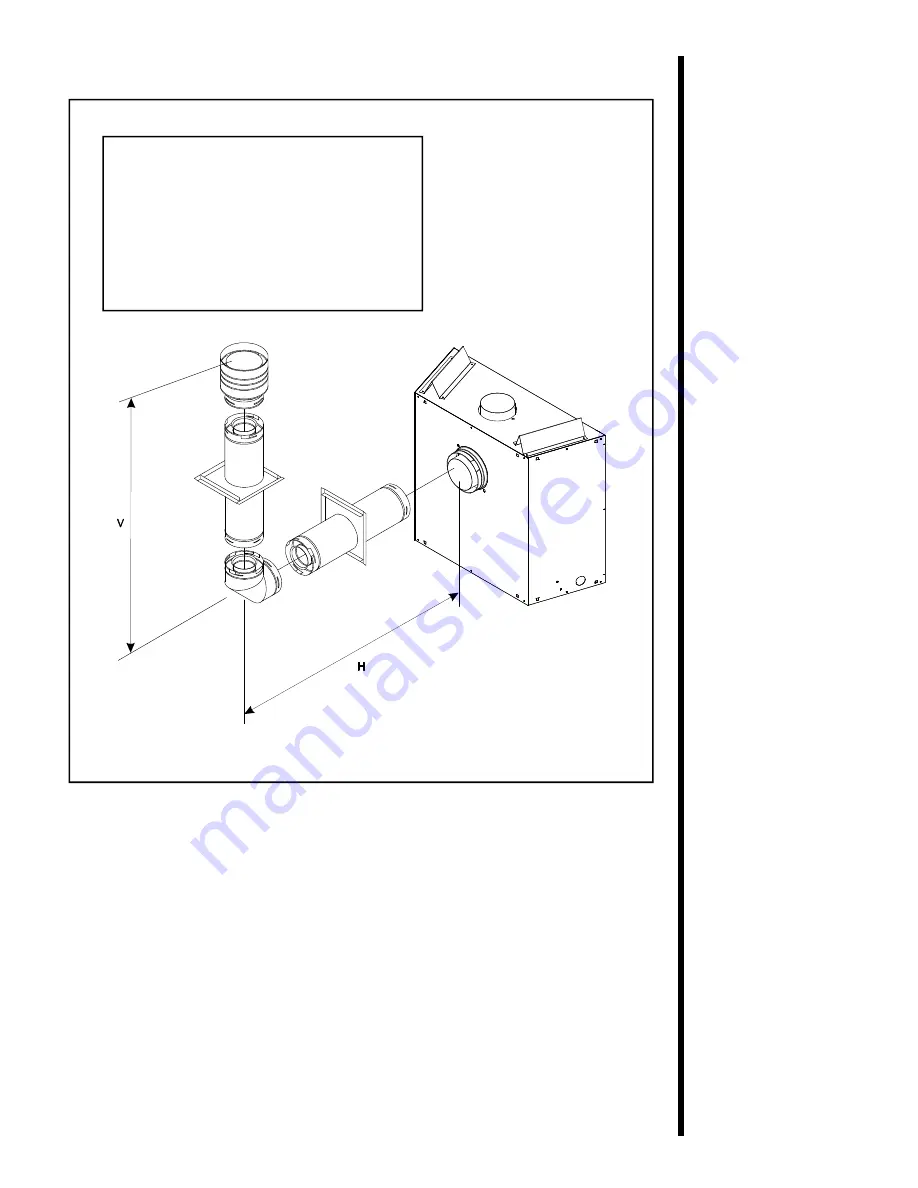
FLUE WITH ONE (1) 90
o
ELBOW
V
H
MIN. 305mm
MAX. 610mm
MIN. 610mm
MAX. 1.22m
MIN. 914mm
MAX. 1.86m
MIN. 1.22m
MAX. 2.48m
V+H = MAX. 12.2m H= MAX. 2.48m
Use D-Series
components only.
Figure 9. Flue with One 90° Elbow
Страница 1: ...questions or concerns For the number of your nearest Heat N Glo dealer please call 1 888 427 3973 Printed in U S A Copyright 2002 Heat N Glo a division of Hearth Technologies Inc 20802 Kensington Blv...
Страница 2: ...n Young children should be CAREFULLY SUPERVISED when they are in the same room as the appliance These units MUST use one of the fluing systems described in the Installing the Fireplace section of the...
Страница 3: ...ling Flue Components 23 C Flue Termination 29 Step 4 Positioning Leveling and Securing the Fireplace 33 Step 5 The Gas Control Systems 33 Step 6 The Gas Supply Line 34 Step 7 Gas Pressure Requirements...
Страница 4: ...STANDARD SL 550TR CE C Advantica Gas Fireplace 90 396 EEC Installation Regulations Before installation check that local distribution conditions nature of gas and pressure and adjustment of the applian...
Страница 5: ...all of the instructions before starting the installation Follow these instructions carefully during the installation to ensure maximum safety and benefit Failure to follow these instructions will void...
Страница 6: ...ctrical wiring Framing and finishing details Whether optional accessories devices such as a fan wall switch or remote control are desired If the fireplace is to be installed on carpeting or tile or on...
Страница 7: ...14mm 32 1 2 827mm 2 1 4 55mm 5 1 16 129mm GAS LINE ACCESS 31 790mm 36 913mm 3 1 2 90mm 8 198mm ELECTRICAL ACCESS 23 3 8 593mm 8 5 8 219mm 6 5 8 168mm 20 1 2 521mm 31 789mm BOTTOM GRILLE COVER ELECTRI...
Страница 8: ...ions Locations and Space Requirements MODEL RECESSED DEPTH SL 550TR CE C 41 3cm The minimum clearance to a perpendicular wall extending past the face of the fireplace is 7 62cm The back of the firepla...
Страница 9: ...Framing should be positioned to accommodate wall coverings and fireplace facing material The diagram below shows framing reference dimensions CAUTION MEASURE FIREPLACE DIMENSIONS AND VERIFY FRAMING ME...
Страница 10: ...or identification NO OTHER FLUEING SYSTEMS OR COMPONENTS MAY BE USED Detailed installation instructions are included with each flue termination kit and should be used in conjunction with this Installe...
Страница 11: ...gure 5 D Series Direct Flue Component Specifications 127mm inner pipe 219mm outer pipe DV 36D 146mm 222mm 298mm DV 12D DV 09D DV 06D DV 48D DV 90D 187mm 156mm 295mm 303mm 149mm 219mm 216mm 164mm DV 45...
Страница 12: ...r pipe 168mm outer pipe NOTE PIPES OVERLAP 34 93mm AT EACH JOINT 235mm 165mm 168mm 168mm 244mm 162mm 162mm 165mm 244mm SL 90D SL 45D 165mm 168mm 146mm 298mm SL 06D SL 12D SL 17 24D 432 610mm SL 09D SL...
Страница 13: ...15 STRAIGHTUP VERTICALFLUE V 12 2m MAX Figure 7 Straight up Vertical Flue Use SL D Series components only...
Страница 14: ...16 STRAIGHTOUTHORIZONTAL FLUE H Max Run 610mm Use D Series components only Figure 8 Straight Out Horizontal Flue...
Страница 15: ...17 FLUE WITH ONE 1 90o ELBOW V H MIN 305mm MAX 610mm MIN 610mm MAX 1 22m MIN 914mm MAX 1 86m MIN 1 22m MAX 2 48m V H MAX 12 2m H MAX 2 48m Use D Series components only Figure 9 Flue with One 90 Elbow...
Страница 16: ...0mm MAX 2 4m MIN 914mm MAX 3 6m MIN 1 22m MAX 4 8m V H MAX 12 2m H MAX 4 8m NOTE For corner installations A 152mm MINIMUM length of straight pipe must be first attached to the fireplace before 90o elb...
Страница 17: ...MAX 1 86 m MAX 3 6 m MIN 1 22 m MAX 2 48 m MAX 4 8 m H MAX 2 48 m H H1 MAX 4 8m V H H1 12 2m MAX Figure 11 Flue with Two 90 Elbows FLUE WITH TW0 2 90 ELBOWS V H H1 MIN 305 mm MAX 610 mm MIN 610 mm MA...
Страница 18: ...4 8m H MAX 4 8m NOTE V V1 H MAX 12 2m FLUE WITH TWO 2 90 ELBOWS MIN 305mm MAX 610mm MIN 610mm MAX 1 22m MIN 914mm MAX 1 86m MIN 1 22m MAX 2 48m MIN 1 52m MAX 4 8m V H H1 MAX 12 2m H H1 MAX 4 8m FLUE...
Страница 19: ...22 m MAX 2 48 m MAX 4 8 m H MAX 2 48 m MAX 4 8 m NOTE V V H H1 9m MAX V H H H1 V H H H1 H2 MIN 305 mm MAX 610 mm MAX 1 22 mm MIN 610 mm MAX 1 22 m MAX 2 48 m MIN 914 mm MAX 1 86 m MAX 3 7 m MIN 1 22...
Страница 20: ...1 22m MAX 4 8m MAX 4 8m V V1 H H1 9m MAX FLUE WITH THREE 3 90 ELBOWS V H H1 MIN 305mm 4 MAX 1 22m MIN 610mm 8 MAX 2 48m MIN 914mm 12 MAX 3 72m MIN 1 22m 16 MAX 4 8m H H1 MAX 4 8m V V1 H H1 MAX 9m FLUE...
Страница 21: ...BOX MUST REMAIN ATTACHED IF THE FLUE SYSTEM IS ATTACHED TO THE REAR STARTING COLLARS SEE FIGURE 15 Venting Out the Top Flue Remove the top flue collar seal cap and the two pieces of insulation inside...
Страница 22: ...s into the fireplace collar or previously installed component end with four 4 equally spaced indented sections When the internal beads of each outer pipe line up rotate the pipe section clockwise abou...
Страница 23: ...y be installed and rotated to any point around the preceding component s vertical axis If an elbow does not end up in a locked position with the preceding component attach with a minimum of two 2 shee...
Страница 24: ...e outlet Figure 18 Installing Support Brackets 4 Seal all outer pipe joints with RTV compound 5 Install Firestops For Horizontal Runs Firestops are REQUIRED on both sides of a combustible wall through...
Страница 25: ...the firestops 1 Cut the hole through the wall Figure 19 Hole and Flue Pipe 2 Position the firestops 3 Place the heat shield to the top 4 Continue the flue run Figure 20 Heat Shield Interior and Exter...
Страница 26: ...80 mm for D series or 254 mm X 254 mm for SL D series pipe hole through the ceiling using the centerpoint previously marked Frame the hole with framing lumber the same size as the ceiling joists 1 Cut...
Страница 27: ...the Installing Flue Components sec tion The termination kit should pass through the wall firestops from the exterior of the building Adjust the termination cap to its final exterior posi tion on the b...
Страница 28: ...anges in the cap 2 Seal the joint between the pipe and the exterior firestop Figure 24 Round and Trapezoid Termination Caps WARNING THE BOTTOM OF THE FLUE TERMINATION CAP MUST BE A MINIMUM OF 305 MM A...
Страница 29: ...f There MUST BE a 25 4 mm clearance from the vertical flue pipe to combustible materials Mark the roof hole accordingly Cover the opening of the installed flue pipes Cut and frame the roof hole Use fr...
Страница 30: ...ROM ROOF TO LOWEST DISCHARGE OPENING 61cm 61cm To seal the roof hole and to divert rain and snow from the flue system Attach a flashing to the roof using nails and use a non hardening mastic around th...
Страница 31: ...the fireplace with non combus tible material such as sheet metal as necessary 4 Secure the fireplace to the framing by nailing or screwing Figure 26 Proper Positioning Leveling and Securing of a Firep...
Страница 32: ...line leading to the Rp 1 2 hook up at the unit This gas inlet connection is ISO 7 Rp 1 2 BSP Rp 1 2 To install the gas supply line When attaching the pipe support the control so that the lines are no...
Страница 33: ...THE GAS CONTROL VALVE OR THE APPLIANCE WILL MALFUNCTION AND THE VALVE WILL BE DESTROYED Optional Accessories Optional fan and remote control kits require that 230 VAC be wired to the factory installe...
Страница 34: ...NG ERRORS CAN CAUSE IMPROPER AND DANGEROUS OPERATION VERIFY PROPER OPERATION AFTER SERVICING Figure 29 Standing Pilot Ignition Wiring Diagram WARNING WHEN FINISHING THE STOVE NEVER OBSTRUCT OR MODIFY...
Страница 35: ...combustible projections above the top front edge of the fireplace See Figures 2 and 3 for other fireplace clearances Only non combustible materials may be used to cover the black fireplace front Figur...
Страница 36: ...d brass trim surround kits as desired Marble brass brick tile or other non combustible materials can be used to cover up the gap between the sheet rock and the fireplace Do not obstruct or modify the...
Страница 37: ...this manual If sooting occurs the logs might need to be repositioned slightly to avoid excessive flame impingement Removing Grate Shipping Support Remove the log pack and hood if applicable Bend top r...
Страница 38: ...and tension springs around the glass door Remove the glass door from the unit Figure 33 Place small pieces of ember material on burner top Figure 34 Do NOT press embers into burner ports Cover the top...
Страница 39: ...ring with the fireplace components is DANGEROUS and voids all warranties A small amount of air will be in the gas supply lines When first lighting the fireplace it will take a few minutes for the line...
Страница 40: ...g Ember Material in the INSTALLERS GUIDE Cleaning Once annually Qualified Brush or vacuum the control Burner Service compartment and burner areas Controls Technician surrounding the logs Checking Peri...
Страница 41: ...43 STANDINGPILOT Figure 35 Burner Flame Patterns MAKE SURE THE FLAMES ARE STEADY NOT LIFTING OR FLOATING Figure 36 Pilot Flame Patterns...
Страница 42: ...ay be out of fuel Check that the pilot flame impinges on the thermocouple Clean and or adjust the pilot for maximum flame impingement Ensure that the thermocouple connection at the gas valve is fully...
Страница 43: ...nimum With the pilot in the ON position disconnect the thermopile leads from the valve Take a reading at the thermopile leads The reading should be 325 millivolts minimum Replace the thermopile if the...
Страница 44: ...l flue cap should slope down only enough to prevent any water from entering the unit The maximum downward slope is 6 mm Tighten the corner Replace if necessary Check for proper installation and freedo...