10
OVERVIEW
Thank you for choosing the SuperPole F.R.S. (floor receptacle system) from
HealthCraft. Please read and understand the instructions in this manual; keep
manual for future reference. It is your responsibility to see that your SuperPole
F.R.S. is properly assembled, installed, and cared for. Failure to follow instructions
in this manual could result in serious injury or death. If you are not equipped to
undertake the outlined work, we would recommend that you have your SuperPole
F.R.S. installed by a qualified contractor.
The SuperPole F.R.S. is a high quality, commercial grade support pole that
interfaces with and is supported by a receptacle that is permanently embedded into
a structural concrete floor. The SuperPole F.R.S. is intended for moderate vertical
load bearing to provide sitting and standing support for people with reduced
mobility. When the pole is removed, the receptacle must be covered with a floor
flush cap to provide a water-tight seal. The maximum user weight for this product is
450lbs / 205kgs. Product is not intended to support full body weight. The SuperPole
F.R.S. is not to be used in any other way than described above.
WARNING - PATIENT ENTRAPMENT (see additional guidelines)
The potential risk of entrapment (limb, neck, head, torso) between the pole and
adjacent item (i.e. mattress, headboard, sidetables, etc.) can be reduced or
avoided by the following strategies:
1. Situate the pole at a distance that is considerably smaller or larger than that
which could result in entrapment.
2. Consider situations that could change with time or usage such as mattress
compression, patient movement, bed position changes due to electrically powered
beds, etc.
3. Realize that this product is not intended as a physical constraint or barrier to
exiting the bed.
LIMITED LIFETIME WARRANTY
Products are covered by a limited lifetime warranty against defects in materials and
workmanship for the original purchaser. Warranty excludes products that have been
damaged through misuse, accidental damage, alteration, normal wear and tear,
wood material and stain, or the use of corrosive or abrasive cleaning products.
Buyer hereby indemnifies, agrees to hold harmless and defend HealthCraft
Products Inc. from and against any and all liabilities, claims, (founded and
unfounded), losses, damages, costs and expenses (including without limitation
consequential damages and reasonable professional fees) resulting from buyers
specification, application, or improper use of goods described hereon; buyers
omission or neglect. HealthCraft Products Inc. does not assume any liability for
damage resulting from services performed by others or faulty installation, misuse or
misapplication of goods sold by HealthCraft Products Inc. HealthCraft Products Inc.
shall not be liable for prospective profits or special, indirect, or consequential
damages, or for the cost of any corrective work done without HealthCraft Products
Inc. prior approval. HealthCraft Products Inc. total liability hereunder shall in no
event exceed the purchase price of the goods specified hereon. Specifications
subject to change without notice.
HealthCraft Products Inc.
2790 Fenton Road
Ottawa, Canada
K1T 3T7
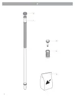
DELIVERY CONTENTS - SUPERPOLE F.R.S.
FIGURE A.
1. Pole
3. Cap
5. NOT INCLUDED: Anchoring Cement or Embedment Grout (hardened bond and
pullout strength min 2000 psi. Suggestions include Hilti HIT-HY150 or Anchorite
Embedment Grout from C.C.Chemicals).
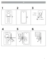
SUPERPOLE PLACEMENT
FIGURE B.
1. BEDROOM - Locate pole adjacent to waistline, and as close to bed as possible
while allowing clearance for bed coverings.
2. BATHTUB ONLY - Locate pole base against tub, approximately half way along its length.
3. SEATING (TOILET or CHAIR) - To provide clearance when standing, locate pole
3-10" / 76mm-254mm forward of the knees, and 2-6" / 51mm-154mm to the side of
knees when sitting.
English
SUGGESTED SUPERBAR POSITIONS (OPTIONAL)
FIGURE B.
4. BEDROOM
A = side support / out of the way
B = in-bed support
C = sitting support
D = standing support
E = transfer support to
walker / wheelchair
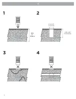
SAFETY CONSIDERATIONS
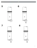
FIGURE C.
1. Ensure min 6" /152mm depth for concrete floor.
2. Ensure hole dimensions are possible in desired location.
3. Do not install if concrete floor is damaged, or not structurally sound.
4. Do not install if there are items embedded in the concrete, such as conduit and pipes.
5. Inspect drive pins at bottom of pole.
6. Do not use if drive pins are crooked.
7. Do not use if drive pins are missing.
8. Do not use if drive pins are damaged.
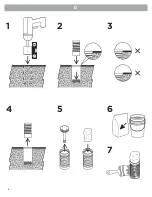
RECEPTACLE INSTALLATION
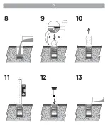
FIGURE D.
1. Drill hole as true vertical with appropriate coring hole saw.
2. Test hole depth by placing receptacle into hole and ensure top surface is flush
with floor.
3. Adjust hole depth accordingly. If receptacle is high, drill hole down further. If
receptacle is low, use metal shims under receptacle to raise.
4. Remove receptacle from hole.
5. Remove the receptacle cap. To protect against grout getting inside the
receptacle, place a rag / towel into receptacle and masking tape. If grout gets in,
immediately remove and clean out. Hardened grout will interfere with proper usage
of the product.
6. As per manufacturer’s directions, clean hole and prepare grout.
7. Apply grout onto the sides of the receptacle.
8. Pour starting amount of grout into the bottom of the drilled hole.
9. Insert receptacle into hole by pushing down and twisting, and ensure top is flush
with floor surface. The grout level (when the receptacle is installed) should be
approx. 0.50" / 13mm from top of floor surface.
- if grout is lower, remove receptacle and add more grout.
- if grout overflows, remove receptacle and take out excess grout.
10. Once grout level is achieved, remove rag / towel from receptacle.
11. Ensure receptacle is held exactly vertical by inserting the FRS pole and
correcting with guidance of a level.
12. Install cap to seal receptacle.
13. After initial grout has hardened, add more grout around the top of the
receptacle and smooth out flush with floor.
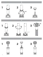
HOW TO REMOVE CAP
FIGURE E.
1. Align drive pins at bottom of pole with holes in cap.
2. Engage drive pins into holes and twist pole to release cap.
3. Remove cap from floor receptacle.
HOW TO INSTALL POLE INTO RECEPTACLE
FIGURE F.
1. Gently lower pole into floor receptacle.
2. Rotate pole until it drops down and stops rotating.
3. Rotate top knob to lock pole into receptacle.
HOW TO STORE CAP INTO KNOB
FIGURE G.
1. Remove rubber cover from knob on top of pole.
2. Insert receptacle cap into knob.
3. Replace rubber cover onto knob.
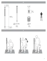
TECHNICAL DATA
See Figure H.
PRODUCT USAGE
See Figure I.
Gate 88
Kanalgatan 45 B
Skelleftea, Sweden
931 23
2. Receptacle
4. Rubber Cover
EC
REP
5.BATHROOM or 6.SITTING
A = side support / out of the way
B = standing or transfer support
C = standing support
D = standing or transfer support
E = standing or transfer support
F = transfer support in/out of bathtub
Содержание SuperPole F.R.S. Series
Страница 1: ...SuperPole F R S FRS FR FRS P DC109 RevC healthcraftproducts com ...
Страница 2: ...2 A 1 4 3 2 5 ...
Страница 3: ...3 B 2 51mm 6 154mm 3 76mm 10 254mm A B C D E A B C E D F A C E B D 4 5 6 1 2 3 ...
Страница 4: ...B 4 C 1 2 3 4 MIN 6 152mm 4 125 4 25 105 108mm Ø 2 2 25 51 57mm ...
Страница 5: ...5 C 5 6 7 8 ...
Страница 6: ...D 6 6 7 5 4 1 2 3 ...
Страница 7: ...D 7 11 13 12 10 9 8 0 50 12 7mm ...
Страница 8: ...1 2 3 1 3 1 2 3 E F G 8 x6 x6 CLICK 2 ...


