background image

17

R8

40

56

46

=

=

18

94

10

84

21

26

40

46

10

22

75

300

31

7

75

656

50

10

16

345 339

21

84

46

75

300

65

7

17

50

345

50

Ø1

2

R8

R8

R8

R8

R8

Ø12

30

0

34

0 345

31

7

50

4

16

74

22

50 75

R8

R8

R8

Ø12

X

B-B

C-C

D-D

A-A

B A

D

D

C

C

X

B A

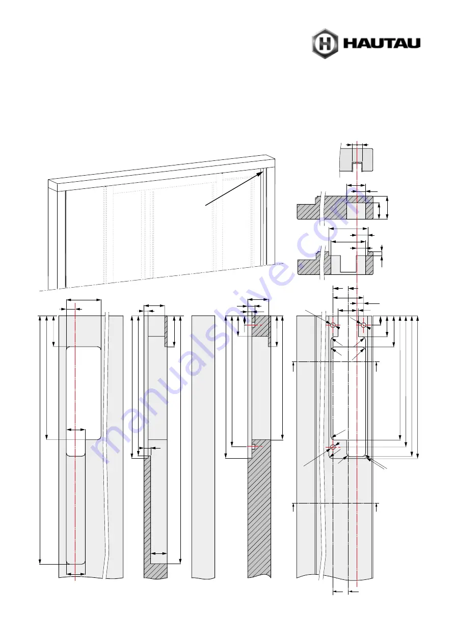
Cut-outs for circuit board

Содержание HS

Страница 1: ...HAUTAU LIFT SLIDE HARDWARE MOUNTING INSTRUCTIONS HS comfort drive Timber Timber Alu covered HAUTAU a MACO Group company Only for use by certified specialists T I MB E R A LU ...

Страница 2: ...18 Locking control and current transition 19 Cut outs for lock case lift drive and hook box 20 Positioning of the drive pin 21 Borings for manual unlocking handle 22 Mounting driving unit 23 Mounting of deflection tooth belt 24 Mounting of cover profile 25 Mounting of tooth belt 26 Connect drive pin with toothbelt 27 Mounting of guide track 28 Mounting circuit board 29 Mounting of magnets 30 Mount...

Страница 3: ...t DIP switch 49 Triggering of Full Init and Home Init 50 First start up Full Init 50 51 Standard operation 52 Teach in run Home Init 53 Safety function check reversing 54 Mounting of the cover electronics 55 Mounting of the cover for manual release locking 55 Fault elimination 56 Maintenance repair 56 Care 57 Technical specification 58 59 Mounting and Installation IR Light curtain 60 65 Installati...

Страница 4: ...d side exit between two separate locations in order to link interior and exterior Use of the HS S comfort drive only for sashes with a weight of max 300 kg integrated anti trap protection Depending on the risk assessment for sash weights of 300 440 kg additional safety devices such as light curtain presence sensor or key switch have to be installed The complete element has to be mounted perpendicu...

Страница 5: ...dapted to its operating environment To fasten the parts use screws with sufficient length so that they can reach into the steel reinforcement in case of PVC profiles No other persons are allowed in the vicinity of the drive when a key switch with off presetting DEAD MAN switch is actuated WARNING Never connect the drive control keypad to 230 V of voltage The drive may only be operated at very low ...

Страница 6: ...r has reached the end position Do not pass through remote controlled doors until the door has stopped Make sure that remote controls do not come into the hands of children and are only used by people who are familiar with the operation of the remotecontrolled door When operating with a remote control there must be visual contact with the door if it does not have an additional safety device light c...

Страница 7: ...can perform all of the steps described If deviating from the instruction steps limitation of warranty claims must be expected Test the drive by trial run Defective drives must be repaired at our factory You may only use original spare parts The readiness for operation has to be checked regularly Care Check all devices and cable connections for external damage and dirt The operability of the contro...

Страница 8: ...household waste at the end of its service life You can return it to free collection points for old electrical appliances in your area or to other centres where they accept old appliances for recycling Contact your local council for addresses of collection points and centres If the electrical appliance or electronic device contains personal data you yourself are responsible for erasing data before ...

Страница 9: ...9 ...

Страница 10: ...1 2 Operation Green lights during movement of the lift sliding drive During Init run Yellow is flashing after finishing the Init run both LEDs are off Yellow lights in case of fault Closing Opening for HS comfort drive only ...

Страница 11: ... on the right Right version sliding sash opening from the right to the left drive module on the left As an example a sash opening to the right is described within these mounting instructions Measurements and procedures for sashes opening to the left have to be adapted accordingly Measurements in mm ...

Страница 12: ... and rotate it to the glazing side until you hear a closure sound 5 Now you can lift the sash by means of a release handle move it to the desired position and move it into the lowered position Locking 6 Insert the manual release handle back into the drive gear spindle and lift the door 6 1 6 2 Slide the door shut and lock it 7 Bring the coupling pin of the lift drive A in matching position to the ...

Страница 13: ...gear 4 Install the unlocking key and rotate it to the glazing side until you hear a closure sound 5 Now you can lift the sash by means of a release handle move it to the desired position and move it into the lowered position Locking 6 Insert the manual release handle back into the drive gear spindle and lift the door 6 1 6 2 Slide the door shut and lock it 7 Bring the coupling pin of the lift driv...

Страница 14: ... 19 17 10 22 23 24 Holz 12 5 3 4 13 18 16 20 19 15 Parts overview Example left version sliding sash opening from the left to the right view from inside optional not included within scope of delivery in case of 1 button control pushbutton on site only Timber ...

Страница 15: ...nics timber 12 Support plate and magnet s 13 Cable for lift drive 14 Cable for control keypad 15 Control keypad 16 Cover for manual release locking in connection with lift drive 17 Lift drive 18 Current transition 19 Contact delivery in connection with lfit drive 20 Emergency release set drive handle and universal key in connection with lift drive 21 Hook locking part 22 Key switch 23 Connection b...

Страница 16: ...shop Tools to be used these have to be provided acc to instructions Preparatory actions Preparation of electrical connection Example left version sliding sash opening from the left to the right view from inside Connecting cable with 1 5 mm cross section Power Pack Drive unit later position of the control keypad empty conduits Ø 16 mm for cable routing within the reveal ...

Страница 17: ...84 21 26 40 46 10 22 75 300 317 75 656 50 10 16 345 339 21 84 46 75 300 657 17 50 345 50 Ø12 R8 R8 R 8 R8 R8 Ø12 300 340 345 317 50 4 16 74 22 50 75 R8 R 8 R8 Ø12 X B B C C D D A A B A D D C C X B A Cut outs for circuit board ...

Страница 18: ...E G G F F G G F F E E E 120 16 R 8 120 16 16 12 5 22 25 6 169 175 12 5 15 5 82 50 92 192 R8 R8 Ø 9 Ø 9 L RAB 2 240 24 Ø 9 12 5 25 22 27 5 54 42 43 12 43 12 86 50 82 66 5 74 L RAB 2 116 Cut outs for drive unit ...

Страница 19: ...8 R8 Ø 16 GM 95 R 8 C B B 17 A B 145 733 733 145 Gr 4 Gr 5 C 1613 2045 D 1794 Gr 4 Gr 5 2342 D 12 Ø12 10 64 32 13 3 12 40 16 16 12 Locking control and current transition hook gear A B C size 4 145 733 1613 size 5 145 733 2045 hook gear size 4 position B is optional hook gear D size 4 1794 size 5 2342 ...

Страница 20: ... 22 8 50 C C C C C A Y B A 166 Gr 4 Gr 5 166 754 754 1634 2066 B C 46 56 300 kg Y Cut outs for lock case A Cut outs for lift drive B Cut outs for hook box C X size 4 125 size 5 292 hook gear A B C size 4 166 754 1634 size 5 166 754 2066 hook gear size 4 position B is optional Y 300 kg 46 56 ...

Страница 21: ...21 145 4 5 x B 22 115 40 Ø7 B 115 10 17 Positioning of the drive pin Bolts may extend by max 4 mm ...

Страница 22: ...40 12 69 83 5 45 5 Ø 20 Borings for manual unlocking handle Bore holes for manual unlocking handle and unlocking key bore until depth of espag box only bore until depth of espag box only Bore holes for cover for manual release locking ...

Страница 23: ... x Mounting driving unit It is recommended to mount on the loose rod By means of both pins position the drive unit below the upper frame within the milled pocket and fasten it with 6 screws Window screw on site ...

Страница 24: ...24 X 4x 4 5 x View X Mounting of deflection tooth belt It is recommended to mount on the loose rod Closing direction Closing direction Window screw on site ...

Страница 25: ...25 X Y 2x 4 0 x 300 500 500 500 Mounting of cover profile It is recommended to mount on the loose rod View X As needed fixed measuere Fastening Cut Y frame with cover support only ...

Страница 26: ...Apply tooth belt form fit by surrounding the deflection wheel Cut tooth belt to length in such a way that it can be fastened in hand tight condition at both ends with 3 teeth each within the clamping part Position top clamping plate as shown on the lower clamping plate and both ends of the tooth belt Connect both clamping plates with 2 screws M4 x 10 4 4 Mounting deflection again Dismantle the def...

Страница 27: ...27 2x M4 x 10 Torx T20 2 2x M4 x 10 Torx T20 2 2x M4 x 10 Torx T20 2 Connect drive pin with toothbelt ...

Страница 28: ... 45 Mounting of guide track Apply double sided adhesive tape to the wood 2 part guide rail passage and fixed area Release guide rail Glue to guide rail Screw the stop bracket to the guide rail double faced adhesive tape passage area fixed area ...

Страница 29: ...29 X 1 2 3 12x 4 2 x 0 1 2 3 5 6 4 6x 4 2 x Mounting circuit board Insert membrane grommet for optional accessories View X Space fot the circuit board Covers flush with each other ...

Страница 30: ...30 3 0 x 20 3x X X 1 4x 3 2 x 8 9 14 338 3 3 Mounting of magnets View X Mounting of the support plates for cover electronics or double faced adhesive tape ...

Страница 31: ...ed in such a way that they cannot get in contact with moving parts The holes to be drilled for cable feed through have to be deburred carefully Danger of material damages Cable to control keypad Attach binder to the cable Strap as a reserve for possible repair Align acc to position of cap for manual release locking pay attention to hole for cable feed through at control keypad ...

Страница 32: ...sition and control keypad Current transition Align acc to position of cap for manual release locking if possible 1 Connect flat plug with the current transition 2 Tighten the current transition with 2 screws 4 0 x to the frame Mounting control keypad ...

Страница 33: ...tallation situation must always be selected in a way that the MACO logo is positioned at the top Turn the strike plates 180 If the strike plates are set too high there is a risk that the handle will be skewed The manufacturing tolerance can be compensated by turning the strikerplates ...

Страница 34: ...34 Mounting of rollers From a sash weight of 200 kg 2 additional 400 kg rollers must be used ...

Страница 35: ...ed In case of retrofitting of the element the sash has to be brought into lowered position by means of the drive handle release set ATTENTION Do not release the handle guide the handle in the locked position because it turns arround quickly due to the sash weight thus could cause heavy injuries ...

Страница 36: ...es Greases for fittings Adhesive lubricant with PTFE in spray form e g OKS 3751 or equivalent IMPORTANT The hook drive gears and the striker plates are to be lubricated before the first startup Mounting of drive support Window screw on site Bolts may extend by max 4 mm ...

Страница 37: ...tion and lower the sash to the drive pin Connect drive pin with the sash High sash weights up to max 300 kg Risk of serious injury due to improper use ATTENTION Do not release the handle guide the handle in the locked positon because it turns arround quickly due to the sash weight thus could cause heavy injuries GEFAHR ACHTUNG WARNUNG DANGER ...

Страница 38: ...y Lock nuts against each other after adjustment of deflection and check of dimension X Put a load of 1 5 kg on the tooth belt Measure dimension X During annual maintenance the tension of tooth belt must be checked The tooth belt must be retensioned if necessary Lift the sash and position it according to dimension 500 ...

Страница 39: ...39 325 Delta PT 3 x 8 Torx T10 500 500 500 Ø 2 5 1 2 3 Cover profile cut to length Length of cover profile L RAB 2 187 As needed Cut to length ...

Страница 40: ...3 3 4 Sliding the sash to the drive pin and reconnect see picture 1 Demontage 1 Loosen the screws from the cover plate 2 Lay cover profile on the sash 3 Open the sliding sash to half of the fixed part 4 Coupling the lift drive 5 Separate drive pin from the sash 6 Remove cover plate from sash 7 Close and lower the sash schließen Mounting cover profile for tooth belt ...

Страница 41: ...e coupling pin A and the drill hole on the bolt into alignment 4 Close by means of the unlocking bowl in the direction of the sash frame to couple the bolt to the drive Bolt must be latched ATTENTION Do not release the handle guide the handle in the locked positon because it turns arround quickly due to the sash weight this could cause heavy injuries ...

Страница 42: ... sash opening from the left to the right view from inside Lift drive Power supply Control keypad HAUTAU bus service connection WLAN box Do not let cables to the circuit board get caught in rotating parts Drive unit If an emergency STOP switch is connected the bridge 1 9 has to be removed also if a connection box will be used refer to page 44 View 90 ...

Страница 43: ...n 1 X1 5 control output for locking control X1 6 ext OPEN control input switching impulse of finger print sensor X1 7 ext CLOSE control input X1 8 ext HAUTAU bus X1 9 emergency stop input X1 10 GND X3 terminal for lift drive X3 1 24V or GND X3 2 GND or 24V X4 terminal for control keypad X4 1 24V red X4 2 HAUTAU bus brown X4 3 GND black X5 terminal for power supply X5 1 24V X5 2 GND X6 HAUTAU bus s...

Страница 44: ...lue emitter and receiver Connection of emergency STOP switch or bridge between 1 and 2 1 24 V 2 Emergency STOP input HAUTAU bus service terminal connection WLAN box 1 24 V 2 HAUTAU bus 3 GND Connection of IR Presence sensor 1 brown and pink 2 red 3 grey 4 blue and green not used without function Connection of key switch Connection of finger print sensor 1 24 V 2 CLOSE 3 OPEN 1 24 V 2 3 Switching i...

Страница 45: ...f 1 button control pushbutton refer to section Connection of 1 button control pushbutton Circuit board drive module HS S comfort drive Lift drive HAUTAU bus Power supply Control keypad Control keypad Power supply 24 V DC red red brown brown black black Lift drive contact delivery Power supply 24 V DC Lift drive HAUTAU bus Control keypad Control keypad red red brown brown black black Slide version ...

Страница 46: ...pad Control keypad red red brown brown black black in case of 1 button control pushbutton refer to section Connection of 1 button control pushbutton WLAN box in case of 1 button control pushbutton refer to section Connection of 1 button control pushbutton Lift drive HAUTAU bus Control keypad red red brown brown black black Electrical connection continuation Connecting diagramm examples Die Adresse...

Страница 47: ...print sensor Signal length 0 5 1 s EMERGENCY STOP switch Lift drive contact delivery Lift drive contact delivery Power supply 24 V DC Power supply 24 V DC red red brown brown black OPEN CLOSE black Lift Slide version WLAN box with EMERGENCY STOP switch Lift Slide version WLAN box without EMERGENCY STOP switch in case of 1 button control pushbutton refer to section Connection of 1 button control pu...

Страница 48: ... switch ATTENTION When using an EMERGENCY STOP the bridge X5 1 and 2 has to be removed OPEN brown brown blue blue green green grey grey red red pink pink CLOSE IR Light curtain receiver plug BLUE IR Light curtain receiver plug BLUE IR Light curtain emitter plug WHITE IR Light curtain emitter plug WHITE Lift drive contact delivery Power supply 24 V DC rot rot brown brown brown brown black black whi...

Страница 49: ...ht version 2 Secondary Scheme C 3 Primary Scheme C 4 automatic optional with finger print sensor ekey DEAD MAN s mode with key switch In case of first start up Full Init or teach in run Home Init the sash runs in AUTOMATIC mode and afterwards in DEAD MAN s mode Press button OPEN the sliding sash has to run OPEN The sash runs approx 100 mm and then stops automatically If the sash does not run OPEN ...

Страница 50: ...he pushbutton box does not sound anymore Mode control element Type of initialization Action Feedback AUTOMATIC mode DIP switch 4 is ON Control keypad Software reset Home Init press STOP button for approx 20 sec yellow green LED Factory reset Full Init press STOP button for approx 30 sec yellow green LED Control push button with pushbutton box Software reset Home Init press pushbutton for approx 20...

Страница 51: ...o CLOSED position When the sash ist closed the system recognizes whether a lift drive exists or not Lift drive exists Sash lowers Initialization is finished Sash remains in lowered position for a few seconds Sash lifts independently Sash slowly opens completely until the end of the element Sash runs in direction CLOSE until position close The anti trap protection and all other safety devices are e...

Страница 52: ...his After adjusting the operating mode switch a factory reset Full Init with complete automatic initialization has to be executed refer to section Triggering of Full Init and Home Init Element is ready for operation Power failure refer to Home Init Press CLOSE at the control keypad Sash closes with normal speed Sash is closed Lift drive exists Sash lowers and locks Sash is readyfor operation No li...

Страница 53: ...ive exists Sash lowers and locks Sash is readyfor operation No lift drive Lock the sash by means of handle Sash remains in position CLOSE Sash is readyfor operation Home Init software reset If DIP switch 4 at the S2 switch is adjusted for DEAD MAN the sash first runs in AUTOMATIC mode and afterwards in DEAD MAN s mode or beep at pushbutton box in case of 1 button control pushbutton in case of 1 bu...

Страница 54: ...he frame or at the sash the object should be covered with a suitable fabric Check was not successful Teach in run Home Init and safety function check reversing have to be repeated If the check was not successful repeatedly the Lift Slide System has to be taken out of operation and disconnected from mains as well as a service company has to be consulted for the purpose of troubleshooting Otherwise ...

Страница 55: ...the cover electronics Mounting of the cover for manual release locking for HS comfort drive only Version timber Cut out in the frame Cut out for bottom cover drive unit horizontal frame 0 flush to bottom edge of frame ...

Страница 56: ...ress the OPEN button in case of normal run everything is ok if the yellow LED continues to light software reset by pressing the STOP button for approx 20 s Home Init both LEDs light for approx 3 s please follow section Teach in run Home Init ifthe STOP button will be pressed for approx 30 s a factoryresetwill be executed Full Init both LEDs lightfor approx 3 s please follow section First start up ...

Страница 57: ...d by for example structural measures or stored goods Use a soft slightly dampened cloth to clean the housing components and the control keypad To prevent damage to the surfaces do not use any caustic chemicals abrasive cleaners or agents containing solvents for cleaning Provide the drive with durable protection against water and dirt ...

Страница 58: ...g conditions yes Maintenance once a year acc to general maintenance guidelines Connection to WLAN Box Address delivered condition 103 Installation and environmental conditions Nominal temperature 20 C Ambient temperature range 5 to 60 C environmental category 1 acc to VdS 2580 Protective system IP 40 acc to DIN EN 60529 Environmental conditions for dry environments only no dew formation no aggress...

Страница 59: ... compliant yes Temperature range 5 to 60 C Protective system IP 40 acc to DIN EN 60529 Max cycles 20 Lift drive Electrical characteristics Rated voltage 24 V DC 15 30 Permitted voltage range 20 4 to 31 2 V DC Max allowable ripple 20 related to rated voltage Current consumption 2 A Switching off OPEN CLOSE built in limit switch Protection class III safety extra low voltage SELV Material and mechani...

Страница 60: ...60 1x 1x 4x Mounting and Installation IR light curtain Connection cable light curtain indoor Light curtain Emitter and Receiver outdoor 2x blue for receiver 2x for emitter Pars overview ...

Страница 61: ...or 46 Operating range 0 8 up to 6 m Max ambient light 75 000 Lux Dimensions 2000 mm L x 12 mm W x 16 mm D Cable length 2 x 5 meter connecting cable Operating temperature 20 C up to 65 C Vibration IEC 60068 2 29 EN 50155 EN 50121 Shock IEC 60068 2 6 EN 50155 EN 50121 EMV Emission EN61000 6 3 EN 50155 EN 50121 EMV immunity EN61000 6 2 EN 50155 EN 50121 Enclosure rating IP 65 Material aluminium Profi...

Страница 62: ...ht and crossed beams A built in calibration feature of each individual beam to eliminate any adjustment suppress light interference or control influence from dirt Automatically adjust the power to provide the optimal operating conditions These features give an outstanding functional reliability Any interruption of the surveillance area by an object or a person will be detected and the output signa...

Страница 63: ...shearing forces that the cable is fixed and conduited safely and with large bending radius fig 3 to avoid dirt on the light curtains to avoid contamination by oil or greasy fluids that during operation no sash cable etc extend into the surveillance field fig 5 to avoid interference with foreign infrared light sources like other light curtains energy saving lamps direct sun light etc at receiver cu...

Страница 64: ...ent The range of detection will be defined by α and X or β and Y and the width of the element The range of detection has to be adjusted in such a way that the function will be ensured Receiver indoor outdoor 1 IR light curtain 2 Control keypad 3 Key switch Mounting and Installation IR light curtain continuation ...

Страница 65: ... sash make sure that a the distance between the cables of the light curtain and possible electromagnetical disruptive factors is as wide as possible b there are no obstacles between the emitter and the receiver Make sure that obstacles does not enter the light path c the edges are properly installed and aligned so that they cannot swing or vibrate and therefore lose line or sight between themselve...

Страница 66: ... remote control as follows For installation and additional equipment please use separate instructions for the presence sensor safety sensor IXIO ST supplied IR Presence Sensor Safety sensor Parts overview BEA remote control Wiring the sensor Test Monitoring Sensor Power Supply Green Bown Pink Grey Red Blue Yellow White Not used Opening output Monitoring Input Safety Input Beam receiver keep sash o...

Страница 67: ...er Box Pushbutton Box HS comfort drive Pushbutton Flush housing deep version 1 Power supply and connection to HS comfort drive circuit board terminal X4 2 Connection for pushbutton 3 Buzzer for signalling within the housing 4 Connecting cable Length 10 m Installation of the Pushbutton Box The Pushbutton Box is designed for installation in an on site flush housing deep version The place of installa...

Страница 68: ...ware will be reset Home Init by pressing the button for about 30 seconds continuously a factory reset Full Init is carried out HS S comfort drive in DEAD MAN s mode to get into this special mode a double click is necessary Only afterwards by pressing the button for about 20 seconds continuously the software will be reset Home Init by pressing the button for about 30 seconds continuously a factory ...

Страница 69: ...ad to safety stop of the HS S comfort drive in case of pressing the button only during opening closing in case of initialization ATTENTION During initialization all safety devices are disabled until the initialization will be finished Confirmation beep in case of software reset Home Init after about 20 seconds To reset the operating button has to be pressed for at least 20 seconds one time Confirm...

Страница 70: ...Type of cable not shielded Number of drives 1 per Pushbutton Box Installation and environmental conditions Nominal temperature 20 C Ambient temperature range 0 C to 40 C Installation situation dry Applicable for outdoor installation no Protection system IP 20 acc to DIN EN 60529 Approvals and certificates CE compliant yes acc to EMC Directive 2004 108 EG and Low voltage Directive 2006 95 EG RoHS c...

Страница 71: ...71 Notes ...

Страница 72: ...ERAUTOMATION WINDOW AUTOMATION Would you like everything from a single source HAUTAU a specialist in sliding products is part of the MACO Group At MACO you get complete solutions for your large surfaces windows and doors for timber PVC and aluminium Experience our versatile system range with comprehensive service included Discover more on www maco eu and www hautau de or contact your customer advi...

Отзывы: