Z-WAVE NETWORK
Z-Wave uses a mesh network topology where any
non-battery powered device acts as a signal
repeater, enabling reliable connections from one
node to the other. Battery powered devices do not
act as repeaters as this would result in high levels
of battery drain.
The frequencies used for Z-Wave are below that of
the normal Wi-Fi band and this enables better
penetration of walls and other items found in all
homes, but in addition to this, the mesh network
means that the transferred data can intelligently
routed by the network to get around obstacles and
thereby obtaining robust whole-home coverage.
Z-Wave typically has a range of about 50 meters in
open air. However walls and other items in the
home will considerably reduce this and therefore it
is recommended that the maximum device spacing
Z-Wave network is around 10 meters. Anything
closer will provide better communications.
In order to have a hierarchy within a wireless
network, various types of Z-Wave device are
specified:
Controller:
As the name implies, these devices are
those that control other Z-Wave devices. Controller
devices are factory programmed with a Home ID
which cannot be changed by the user.
Slave:
Slave devices are those that are controlled
by controllers. Slave devices do not have a pre-
programmed Home ID, but instead they take the
Home ID assigned to them by the Z-Wave network
controller.
Routing slave:
This form of Z-Wave slave is one
that knows its neighbors and has partial knowledge
of routing table. It can reply to the node from
which it has received the message. It can also send
unsolicited messages to a number of predefined
nodes to which it has routes.
Z-Wave networks can be linked together for even
larger deployments. Each Z-Wave network can
support up to 232 Z-Wave devices allowing the
flexibility to provide sufficient devices for a
complete automated home.
Z-WAVE NETWORK
INCLUSION / EXCLUSION
On factory default the device does not belong to
any Z-Wave network. The device needs to be
added to an existing wireless network to
communicate with the devices of this network. This
process is called Inclusion. Devices can also be
removed from the network. This process is called
Exclusion. Both processes are initiated by the
primary controller of the Z-Wave network. This
controller is turned into exclusion respective
inclusion mode. Inclusion and Exclusion is then
performed doing a special manual action right on
the device.
INCLUSION
Bring the module at max. 1 meter distance
from the main controller.
Connect the module to power supply.
Set the Z-Wave controller into INCLUSION
mode (adding new device to the Network).
Triple click the Z-Button on the front panel.
Be patient until the inclusion process is
completely finished. Multichannel
devices usually need a bit more time
for complete configuration.
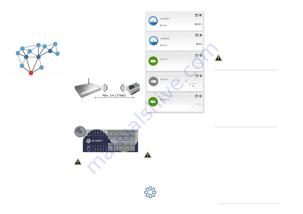
After the inclusion, it will appear a separate
instance (Node) for each relay channel as well as
additional nodes for the network Voltage, and
Frequency, Instant Current, Active Power, Power
Factor and Energy Usage. You can hide
unwanted Nodes and rename those which you
need. Depending on the model of your main
controller, you can also edit Node icons in order
to suit your current project needs.
EXCLUSION
Bring the module at max. 1 meter distance
from the main controller.
Connect the module to power supply.
Set the Z-Wave controller into EXCLUSION
mode (remove device from Z-Wave Network).
Triple click the Z-Button on the front panel.
After the EXCLUSION, all user
configuration parameters of the
module will be automatically set to
their default values.
CONFIGURATION PARAMETERS
This Z-Wave product is designed to work out of the
box after inclusion. However certain configuration
can customize its functionality and fit it to your
specific project needs.
Configuration parameters are
accessible from the main controller
User Interface (UI). You should find
detailed instruction on configuration
procedure into your main controller
User Manual.
When proceeding with parameter modification,
please refer to the parameter Range and Data
Type, as they are specified below:
Reporting time
Minimum time interval between power meter
data reports.
Parameter No:
11
Data type: 1 byte
Default value: 30 sec
Range: 1 – 255 sec
Decreasing the reporting time to less than
5 seconds could flood your Z-Wave
network, strongly impacting the network
communication.
Power Up Memory
When Power Up memory is active, the module will
save actual status of all outputs in case of power
break. After restoring the supply, all outputs will be
switched to their previously saved statuses.
Parameter No:
64
Data type: 2 bytes
Default value: 0 (inactive)
Available Settings:
1
– Active
0
(or any other number) - Inactive
Button Type
(separate for each channel)
Parameters No:
65
to
74
(for Channel 1 to 10)
Data type: 2 bytes
Default value: 1
Available Settings:
1 – PUSH BUTTON
(Each push is changing the
output status from ON to OFF, or vice versa).
2 – TOGGLE SWITCH
(Each changing the
switch position will change the Output between ON
and OFF statuses).
3
– FOLLOWER SWITCH
(The output is
following the status of the switch: open switch –
inactive output, closed switch – active output).
ANY OTHER
number
will disable the local
control of this channel (remote control over the
Z-Wave network will remain active).


