12
3.3 DNA Delivery Into Cells Using
Electroporation (cont’d)
3.3.2 AgilePulse
™
Electroporation (cont’d)
Electrode
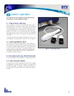
Electrodes used in ex vivo and in vivo electroporation are quite
different. In ex vivo electroporation, the cells are generally placed
in an aqueous ionic medium in a chamber that has parallel plate
metal electrodes. This configuration produces very uniform
electric fields. For in vivo electroporation the electric fields must
be established in human tissue in the body. In this configuration
parallel plates are not practical for vaccine delivery.
For in vivo use two parallel rows of needles are used. This
configuration was first published in an abstract form by Dr. Julie
Gehl in 1997 (Herlev Hospital, Denmark).
Parallel row arrays must be carefully designed to produce
electric field intensities as close to uniform as possible to ensure
as many cells as possible are exposed to the same field. The key
parameters are:
• Number of needles in each row
• Diameter of the needles
• Spacing of the needles in the row
• Space between the two rows
In general the more needles per row and the greater the spacing
between the rows, the closer the electric field approaches that of
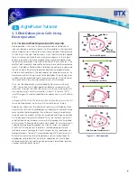
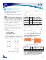
a parallel plate. As an example, the calculated electric field for two
needles per row is presented below:
As the spacing between the rows increases the electric field
rapidly falls off and cold spots form pores in the cells and vaccine
delivery does not occur.
The AgilePulse
™
needle electrodes are specifically designed to
produce near uniform electric fields in the treatment volume.
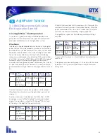
There are currently three ID electrodes available.
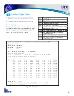
Figure 3-3 Two Needles per Row Field
Model No. Row
Space
Needle/
Row
Needle
Diameter
Needle
Length
Use
47-0040 4 mm
4
0.3 mm
2 mm
Animal
Only
47-0050 4 mm
6
0.3 mm
2 mm
Animal
Only
47-0060 6 mm
6
0.3 mm
2 mm
Animal
Only
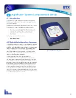
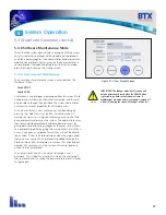
The electric field coverage is presented in Figure 3-4.
Figure 3-4: IDA-4-6-2 and IDA-6-6-2 electric field coverage
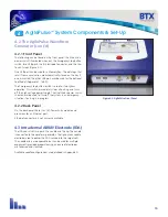
The recommended bleb placement for the IDA-4-6-2 and
IDA-6-6-2 electrodes is shown in Figure 3-5.
The total bleb volume for each is approximately:
There is a significant tradeoff between wider row spacing and
larger delivery volume and pulse amplitude. As pulse amplitude
increases so does pain of the applied pulse voltage.
Figure 3-5: Bleb Formation ID-4-6-2 and ID-6-6-2
Model
No.
Area
Depth Volume
(approx)
Pulse Voltage
V/d=
1000 V/cm
Pulse Voltage
V/d=
1500 V/cm
47-0050
8.7 mm
2
x2
2 mm 50-90 µl 400
600
47-0060
15.6 mm
2
x2
2 mm 100 µl
600
900
4 mm
6 mm
4 mm
6 mm
4 mm
6 mm
AgilePulse
™
Tutorial
3


