Harsco Industrial MACH C1500GG Скачать руководство пользователя страница 47


MACH® Gas-Fired Boiler 


Page  47 


6.0   PARTS/TECHNICAL SUPPORT 

Spare parts and replacement parts can be ordered from Harsco Industrial, Patterson-Kelley by calling toll free (877) 
728-5351.    The fax number is (570) 476-7247.  Technical information is also available at the above number and at 
the Harsco Industrial, Patterson-Kelly website www.harscopk.com. 


Use of Non-Factory-Authorized replacement parts are not recommended for this 

equipment.  All control components are engineered for safety and are designed to work in unison with 
each of the other components.  Use of non-factory-authorized replacement parts jeopardizes the 
functionality of the safety features as well as the performance of the boiler. 

When ordering replacement parts please have the 

model number

 and 

serial number

 of your boiler available. 

Typical schematic drawings are shown on the following pages.  Drawings specific to your particular boiler can also be 
supplied by your local Harsco Industrial, Patterson-Kelley representative. 


6.1 

W

IRING 

D

IAGRAMS


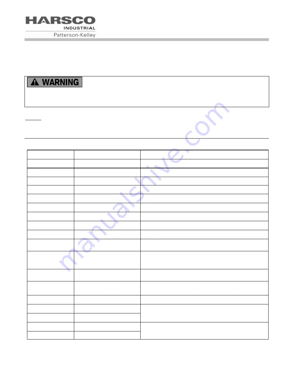
6.1.1  Terminal Block Assignments 

– High Voltage Circuit (TB2) 

Terminal Number 

Label 

Description 

120 VAC LINE 

Boiler Supply Power, 120 VAC, 1 ph , 60 Hz 

120 VAC NEUTRAL 

Boiler Supply Neutral, 0 VAC 

120 VAC NEUTRAL 

Neutral for use with TB2-10, Switched Output 

120 VAC NEUTRAL 

Neutral for use with TB2-11, 3 Way Valve 

120 VAC NEUTRAL 

Neutral for use with TB2-12, DHW Pump Contactor 

120 VAC NEUTRAL 

Neutral for use with TB2-13, CIRC Pump Contactor 

120 VAC NEUTRAL 

Neutral for use with TB2-14, Damper Output 

GROUND 

Boiler Supply Ground, 0 VAC 

GROUND 

Boiler Supply Ground, 0 VAC 

10 

120VAC SW OUTPUT 

120V AC output when boiler is switched on (4 amp 
max) 

11 

120VAC 3 WAY VALVE 

120V AC output during CH Mode.  3 way valve is 
normally closed (not powered) for DHW, and powered 
open for CH Mode.   

12 

120VAC DHW PUMP CNTR 120V AC output when boiler is in DHW Mode (pilot duty 

only) 

13 

120VAC CIRC PUMP CNTR 120V AC output when boiler is in CH Mode (pilot duty 

only) 

14 

120VAC DAMPER 

120V AC output when boiler is enabled (pilot duty only) 

15 

MASTER ALARM RELAY 

This circuit closes when the boiler is in an alarm state 

16 

MASTER ALARM RELAY 

17 

FLAME DETECTED RELAY  This circuit closes when the boiler is firing 

18 

FLAME DETECTED RELAY 

Содержание MACH C1500GG

Страница 1: ...erson Kelley 100 Burson Street East Stroudsburg PA 18301 Telephone 570 476 7261 Facsimile 570 476 7247 www harscopk com MACH C1500GG C2000GG Rev 1 01 4 28 11 C S A Design Certified Complies with ANSI Z21 13 CSA 4 9 Gas Fired Low Pressure Steam and Hot Water Boilers ASME Code Section IV Certified by Harsco Industrial Patterson Kelley C S A Design Certified Complies with ANSI Z21 13 CSA 4 9 Gas Fire...

Страница 2: ...Adjustment 34 4 0 OPERATION 37 4 1 General 37 4 2 Normal Lighting and Shut Down Procedures 37 4 3 Typical Boiler Utility Requirements 38 5 0 MAINTENANCE 39 5 1 Maintenance and Inspection Schedule 39 5 2 Cleaning the Burner 41 5 3 After All Repairs or Maintenance 41 5 4 Sequence of Operation 42 5 5 Troubleshooting 43 6 0 PARTS TECHNICAL SUPPORT 47 6 1 Wiring Diagrams 47 6 2 Boiler Parts List 51 7 0...

Страница 3: ...supplier It is essential to read understand and follow the recommendations of this manual before installing operating or servicing this equipment Installation and service must be performed by a qualified and knowledgeable individual who has been trained on the MACH boiler The same features which permit this boiler to achieve high efficiency performance make it unlike most other boilers of this gen...

Страница 4: ...ion Additional equipment such as temperature sensors pumps flow switches balancing valves and check valves will be required for satisfactory operation of any system Harsco Industrial Patterson Kelley cannot be responsible for the design or operation of such systems and a qualified engineer or contractor must be consulted 2 0 SAFETY 2 1 GENERAL The MACH gas fired boiler must be Installed operated a...

Страница 5: ...above are affixed to your boiler Although the labels are of high quality they may become dislodged or unreadable over time Contact Harsco Industrial Patterson Kelley toll free at 877 728 5351 for replacement labels NOTICE NOTE NOTICE is the preferred signal word to address practices not related to personal injury The safety alert symbol is not used with this signal word indicates a potentially haz...

Страница 6: ...onents could be hot Do not touch piping or stack surfaces during operation or immediately after shutdown of the boiler Burn hazard Hot fluids Use caution when servicing or draining the boiler Fire and explosion hazards Use caution when servicing burner Propane LPG is heavier than air and may linger in the combustion chamber vent lines or elsewhere Gas leak hazard Make sure the burner is installed ...

Страница 7: ...h all applicable regulations A condensate neutralization kit is available Please contact your local Harsco Industrial Patterson Kelley representative 2 5 5 Pressure Hazards Pressure hazard Hot fluids Install isolation valves on boiler water inlet and outlet Make sure isolation valves are closed before servicing boiler Pressure hazard Hot fluids Annually test safety relief valve for proper operatio...

Страница 8: ...by the authorities having jurisdiction Authorities having jurisdiction should be consulted before installations are made Within the US and in the absence of such local requirements this boiler should be installed using the National Fuel Gas Code ANSI Z223 1 NFPA 54 latest edition In Canada the equipment shall be installed in accordance with the current Installation Code for Gas Burning Appliances ...

Страница 9: ...els may be left attached The boiler must be level to function properly To assist in leveling the boiler the four 4 adjustable leg bolts 1 2 13 NC must be installed The adjustable legs are also necessary to prevent distortion of the cabinet twisting etc in addition to leveling Additionally there are three holes in the front and rear of the base that may be used for seismic anchoring 3 3 3 Clearance...

Страница 10: ... earth ground green wire and neutral is required to avoid nuisance shutdowns Do not ground through the conduit It is also important that proper polarity be maintained The electrical junction boxes are located at the front sides of the boiler A detailed schematic of the connections is shown in section 6 1 3 4 1 High Voltage TB2 Terminal Block The boiler power circuit requires 120 VAC 60 hertz with ...

Страница 11: ...t prevents the boiler from running This circuit is energized by the boiler with a 5V potential Devices connected to these terminals must be rated for 5V Outdoor Temp Sensor TB1 5 and TB1 6 are connected to the outdoor temperature sensor The temperature control must be programmed to run an outdoor air schedule The outdoor air sensor and programming help are available from the local Harsco Industria...

Страница 12: ...al or Direct Vent configuration In the US provisions for combustion and ventilation air must be in accordance with NFPA 54 ANSI Z223 1 National Fuel Gas Code latest edition or applicable provisions of the local building codes In Canada combustion and ventilation air openings shall comply with CAN CSA B 149 1 Natural Gas and Propane Installation Code For correct installation of vent system read all...

Страница 13: ...s not certified for use with PVC nor CPVC venting Use of PVC or CPVC vent may result in vent failure and possible serious injury or death Table of Acceptable Materials for Venting Systems Manufactured Venting US and Canada Factory Fabricated Metallic Vent Systems listed and labeled to UL1738 Titled Venting Systems for Gas Burning Appliances Categories II III and IV Table of Applicable Vent Materia...

Страница 14: ...zontal duct that communicates to the outdoors Minimum free area of the opening is 1 square inch for each 3000 Btu hr 700 mm 2 kW of installed appliance input capacity and Not less than the sum of the areas of all vent connectors in the room When using two permanent openings one opening shall commence within 12 inches above the floor and the other within 12 inches below the ceiling preferably on op...

Страница 15: ...tion air opening defined in paragraph A D When combustion air is supplied by natural airflow into a space containing both types of appliance described in paragraphs B and C the cross sectional area of the opening shall be not less than the sum of the cross sectional areas for all appliances in the space as calculated by the applicable method This opening is in addition to the ventilation air openi...

Страница 16: ...Category IV operation Category II appliances operate with a non positive vent static pressure and with a vent temperature that may cause excessive condensate production in the vent There are several requirements for reliable operation of the boilers under Category II conditions 1 A stainless steel vent adapter is required to mate the boiler exhaust connection and the vent pipe See the table below ...

Страница 17: ...on the end limit switch makes contact and closes the external interlock circuit allowing the boiler to fire The diagram below shows the wiring necessary to install the normally closed motorized damper Boiler Size Nominal Stack Size Stainless Vent Adapter Normally Closed Motorized Damper A B C D C1500GG C2000GG 10 2630000226 1004906945 10 10 13 3 38 Use caution if installing a barometric damper in ...

Страница 18: ...ference NFPA 54 ANSI Z223 1 National Fuel Gas Code Do not locate intake or exhaust terminations directly above a walkway dripping of condensation can cause icing of the walking surface Maintain a minimum clearance of 4 ft 1 22 m horizontally from any electric or gas meter regulator or relief equipment Conventional Vent Systems Clearances The following termination clearance requirements are for con...

Страница 19: ...nces are adjacent the exhaust must terminate at least 10 feet horizontally or three feet vertically from the air intake of another appliance Interior Component Clearances All vent system components shall be installed so as to maintain the following required minimum clearances Combustible Non Combustibles Unlisted single wall metal pipe Do NOT Use Do NOT Use Single wall CPVC pipe Do NOT Use Do NOT ...

Страница 20: ...gases into occupied spaces The connection from the boiler to the vent should be as direct as possible and the upward slope of any horizontal breaching should be at least 1 4 inch per linear foot The complete exhaust with drain system is shown in the figure below The appliance connector should incorporate provisions to drain condensate formed in the vent system The connector shall include a drained...

Страница 21: ...terminated as illustrated in section 3 5 5 A birdscreen with 1 x 1 openings is recommended for the termination Harsco Industrial Patterson Kelley does not recommend using a vent rain cap of any type 3 5 4 Venting for Multiple Boilers The venting instructions in this manual apply to a single boiler Venting systems for multiple boilers must be designed by experienced and knowledgeable professionals ...

Страница 22: ... Duct Connection to Boiler Connect the air supply duct to the 10 OD collar on the top of the boiler Fasten the duct to the collar with sheet metal screws at 90º angles Seal the joint 3 5 5 3 Intake Exhaust Layout The MACH Boilers C1500GG C2000GG are certified for direct sidewall venting with a sidewall air inlet only Both the air inlet and the exhaust vent must terminate on the same wall of the bu...

Страница 23: ...er 5 minutes of main burner operation Use the flame of a match or candle or smoke from a cigarette cigar or pipe 6 After it has been determined that each appliance remaining connected to the common venting system properly vents when tested as outlined above return doors windows exhaust fans fireplace dampers and any other gas burning appliance to their previous conditions of use Any improper opera...

Страница 24: ...atural Gas per Hour Pressure Drop of 0 5 inch Water Column Equivalent Length of Pipe in feet 90º Ell Feet Tee Feet 20 40 60 80 100 150 200 1 2 0 622 1 55 3 1 120 82 66 57 50 40 35 3 4 0 824 2 06 4 12 250 170 138 118 103 84 72 1 1 049 2 62 5 24 465 320 260 220 195 160 135 1 1 4 1 380 3 45 6 9 950 660 530 460 400 325 280 1 1 2 1 610 4 02 8 04 1460 990 810 690 620 500 430 2 2 067 5 17 10 3 2750 1900 ...

Страница 25: ...st be capped It is imperative that the natural gas line be connected to the 1 1 2 connection and the propane line be connected to the 1 1 4 connection Incorrect gas connections could result in serious injury death and or property damage It is recommended to close the ball valve for the non selected fuel 3 7 BOILER WATER PIPING 3 7 1 Piping Design Water Flow in System For proper water flow requirem...

Страница 26: ...nd hot water the control system should be configured so as to limit the time rate of change of temperature at the boiler Consult your authorized Harsco Industrial Patterson Kelley boiler representative for application guidance 3 7 1 2 Piping With Air Handling Units The boiler piping system of a hot water heating boiler connected to heating coils located in air handling units where they may be expo...

Страница 27: ...ean water is essential to maximum efficiency and long life of the boiler Relief Valve Piping Each boiler is supplied with a pressure relief valve sized in accordance with ASME requirements Lower pressure relief valves are available contact your Harsco Industrial Patterson Kelley representative The relief valve should be piped to a suitable floor drain Reducing couplings or other restrictions are n...

Страница 28: ...BTU input MACH Boiler Gal of Condensate per hour maximum C1500GG 15 C2000GG 20 3 7 4 Flushing and Filling Water Quality The MACH boiler heat exchanger is made of an aluminum alloy The heat exchanger requires proper water conditions to remain efficient and function properly NOTICE Under no circumstances should petroleum based cleaning or sealing compounds be used in the boiler system NOTICE Under n...

Страница 29: ...lves have been piped to an acceptable drain refer to Section 3 7 9 Condensate piping is properly connected refer to Section 3 7 10 Verify system water quality is within specifications refer to Appendix 3 3 9 SAFETY CHECKS The following checks of safety systems must be made before putting the boiler into normal operation Before firing the boiler refer to Sections 4 1 and 4 2 for information on the ...

Страница 30: ...e high limit switch must be manually reset prior to resetting the boiler at the display panel Readjust the high limit thermostat to the desired setpoint 3 9 4 Test of Gas Pressure Switches Low Gas Pressure Switch The boiler is furnished with two low gas pressure switches one for both gas connections The operation of these switches must be checked by slowly closing the main gas cock while the burne...

Страница 31: ...ion by means of six push buttons MENU BACK ENTER UP DOWN and RESET as shown above The buttons across the bottom are used to navigate through the various screens The four line screen shows boiler operating information on various screens The display screen is backlit for ease of viewing Pressing any key will illuminate the backlight The standby screen is shown upon startup This screen shows the date...

Страница 32: ... BLR OP 1 CH mode 0 CH settings Setpoint 180 F BLR OP 1 CH mode 0 CH settings Setpoint 180 F BLR OP 1 CH mode 0 For example selecting the Setpoint parameter opens up a screen that allows the setpoint to be changed CH settings Setpoint Value 180 F Range 45 F 185 F CH settings Setpoint Value 180 F Range 45 F 185 F The up or down buttons are used to adjust the CH setpoint up or down as desired The en...

Страница 33: ...switches and components The ERRORS menu has information about the boiler status at the time of an error The PARAMETERS menu allows the user to set up selected boiler functions and operating modes The CONFIGURATION menu covers basic display information such as language units date time etc The CASCADE menu is used to sequence multiple boilers up to 24 max in a Master Member network system Use of thi...

Страница 34: ...onents Each boiler is furnished with a manual shut off valve which has an integrated test port This port is located on the upstream side of the valve body for measuring supply pressure See figure right The air flow is pre set at the factory prior to shipment Gas flow is dependent primarily on fan speed not upstream gas pressure The air gas ratio may have to be adjusted to obtain proper combustion ...

Страница 35: ...is labeled and adjusted for a specific fuel The gas valve in the rear is for NATURAL GAS NG The gas valve in the front is for PROPANE GAS LP Check the combustion using a combustion analyzer and adjust the fuel air ratio of the valve being used according to the procedures below For initial startup both Natural Gas and then Propane should be fired and the combustion of each should be adjusted indivi...

Страница 36: ...ing rate of the boiler Check combustion readings using a combustion analyzer If combustion readings are not in accordance with Table of Combustion Exhaust Settings adjust as follows Remove the gray cap on the gas regulator using a slotted screwdriver This will expose the low fire adjustment screw Using a TORX T40 or a 5 mm hex wrench adjust the low fire screw on the pressure regulator see the figu...

Страница 37: ... in the system Turn on electrical supply and open the gas supply valves to the boiler 2 Turn the on off switch to the on position If an error is indicated see Section 5 5 of this manual to troubleshoot the problem and take the necessary corrective action before proceeding 3 Set the desired high temperature limit and operating temperature The controller will now complete the automatic firing sequen...

Страница 38: ...Gas 1030 Btu cu ft Gas Rate CFH Output Capacity Btu hr C1500GG 1 500 000 Less than 15 1456 1 440 000 C2000GG 2 000 000 Less than 15 1942 1 920 000 Note The heat exchanger is constructed and stamped for 100 psig maximum operating pressure and 200º F maximum temperature If overheating occurs or the gas supply fails to shut off do not turn off or disconnect the electrical supply to the pump Instead s...

Страница 39: ... the display panel Observe any unusual noises or operating conditions and make the necessary corrections Notify responsible individuals for required corrective action or repair Check daily to be sure that the boiler area is free and clear of any combustible materials including flammable vapors and liquids 5 1 2 Weekly Observe the conditions of the main flame A normal high fire flame is blue and or...

Страница 40: ...f any soot or foreign material that may have accumulated See Section 5 2 on Cleaning the Burner Check for corrosion of the burner and its parts If there is evidence of deterioration or corrosion replace immediately Inspect combustion chamber when the burner is removed for inspection Note any signs of deterioration Clean as necessary 3 Inspect and clean heat exchanger Remove the various covers to i...

Страница 41: ...front door of the boiler 4 Disconnect the two electrical connections to the blower 5 Remove the ignition electrode 6 Remove the six screws on the bottom of the blower 7 Remove the three nuts holding the blower outlet on the boiler casting 8 Pull the blower w outlet and set aside Inspect burner gasket replace if damaged 9 Reaching inside the burner carefully remove the burner Clean using low pressu...

Страница 42: ...ally below 7 After ignition the fan may be driven to low fire before the boiler is released to modulation 8 The control modulates the firing rate between low and high fire to maintain the desired outlet water temperature 9 The burner will continue firing until the outlet water temperature reaches set point plus hysteresis Off Differential At this temperature the fuel supply is shut off and the com...

Страница 43: ...art the sequence at Step 4 5 5 3 Low Gas Pressure The low gas pressure switch opens when there is or has been insufficient gas pressure available for proper operation of the boiler If an external gas supply shut off valve is closed for any reason a low gas condition will result Locking LOW GAS PRESSURE is shown on the display the burner operation is interrupted and the boiler locks out When proper...

Страница 44: ...AME FAILURE is shown on the display The cause of flame failure must be diagnosed and repaired before the control is reset When IGNITION FAILURE is shown on the display the boiler did not light during a trial for ignition Check that the spark electrode ignition wire and gas valve are functioning properly When FLAME FAILURE is shown on the display the boiler lost the flame during run Check that the ...

Страница 45: ...Flame Flame detected before boiler gas valve opened during pre purge A30 HIGH GAS PRESSURE High Gas Pressure Error The gas pressure is too high and has tripped the HGPS or both gas valves have opened at the same time A31 LOW GAS PRESSURE Low Gas Pressure Error The gas pressure is too low and has tripped the LGPS A32 INTERAL ERROR 23 Internal Error 23 Call for service A33 FAN WRONG SPEED Wrong Fan ...

Страница 46: ...lame detected when no flame should be present E21 LOW FLOW ILK Low Water Flow or Open Interlock Circuit E21 converts to A07 after 5 minutes E22 NO GROUND 60 HZ ERR No Ground error No ground connected or voltage on ground E23 LINE FREQUENCY ERR Line Frequency Error Line frequency deviates from 60Hz by more than 2 E24 FAULTY GROUND Faulty Ground Ground Earth connection is not functioning correctly E...

Страница 47: ...1 1 Terminal Block Assignments High Voltage Circuit TB2 Terminal Number Label Description 1 120 VAC LINE Boiler Supply Power 120 VAC 1 ph 60 Hz 2 120 VAC NEUTRAL Boiler Supply Neutral 0 VAC 3 120 VAC NEUTRAL Neutral for use with TB2 10 Switched Output 4 120 VAC NEUTRAL Neutral for use with TB2 11 3 Way Valve 5 120 VAC NEUTRAL Neutral for use with TB2 12 DHW Pump Contactor 6 120 VAC NEUTRAL Neutral...

Страница 48: ...DHW STAT OR SENSOR Domestic Hot Water sensor or thermostat 8 DHW STAT OR SENSOR 9 HEADER TEMP SENSOR Header temperature sensor 10 HEADER TEMP SENSOR 11 DHW FLOW SWITCH Domestic Hot Water flow switch 12 DHW FLOW SWITCH COMMON DHW flow switch indicates potable water flow usage 13 0 10V ANALOG INPUT Variable Input VDC for remote control of boiler 14 0V ANALOG INPUT 0V for use with TB1 13 15 For Futur...

Страница 49: ...MACH Gas Fired Boiler Page 49 6 1 3 MACH Boiler C1500GG C2000GG Wiring Diagram ...

Страница 50: ...MACH Gas Fired Boiler Page 50 6 1 4 Dual Fuel Control Wiring MACH C1500GG C2000GG ...

Страница 51: ...MACH Gas Fired Boiler Page 51 6 2 BOILER PARTS LIST 6 2 1 Main Assembly Mark Description 1 Cabinet Top 2 Boiler Outlet 3 Boiler Inlet 4 Blower Burner Assembly 5 Front Control Panel 6 Cabinet ...

Страница 52: ...er 1 Terminal Block 2 TB2 120V 7 10 Amp Circuit Breaker 2 High Temperature Limit 8 ENVI Control Main Board 3 Terminal Block 1 TB1 Low V 9 ENVI Control Interface Board 4 Air Switch on back 10 Low Water Cut Off Board 5 High Exhaust Back Pressure Switch HEBPS on back 7 6 10 8 9 5 4 1 2 3 ...

Страница 53: ...1 Blower Outlet Gasket 2 Blower Outlet Transition 3 Burner Gasket 4 Burner 5 Ignition 6 Sight Glass Window 7 Outlet Water Manifold 8 Heat Exchanger Sectional Castings 9 Relief Vavle 10 Inlet Water Connection 11 Boiler Drain Valve 12 Condensate Collector w Rear Drain 13 Inlet Flow Pipes ...

Страница 54: ...lve 1 1 2 2 Natural Gas Automatic Valve 3 Natural Gas Low Pressure Switch 4 Propane Gas Inlet Valve 1 1 4 5 Propane Gas Automatic Valve 6 Propane Gas Low Pressure Switch 7 Automatic Gas Valve Sensing Line 8 High Gas Pressure Switch 9 Secondary Manual Gas Shutoff Valve 10 Venturi 11 Blower w Motor 1 2 5 6 8 10 7 11 3 4 9 ...

Страница 55: ...n F Any failure resulting from misuse modification not authorized by Seller in writing improper installation or lack of or improper maintenance G Equipment furnished by the owner either mounted or unmounted or when contracted for by the owner to be installed or handled H Leakage or other malfunction caused by 1 Defective installations in general and specifically any installation which is made a in...

Страница 56: ...l Yes No Yes No Efficiency Comb Air Pres intake w c w c F Water Outlet temperature F 3 Flow through boiler GPM 4 Operating Temperature Setpoint F from internal OR external control 5 Stack Pressure measured where stack exits boiler w c High w c Low 6 Approximate stack lengths Ft Horizontal Ft Vertical 7 Incoming Electrical Power Volts a c Less than 1 volt between neutral and ground 8 Sytem Water pH...

Страница 57: ... No Efficiency Comb Air Pres intake w c w c F Water Outlet temperature F 3 Flow through boiler GPM 4 Operating Temperature Setpoint F from internal OR external control 5 Stack Pressure measured where stack exits boiler w c High w c Low 6 Approximate stack lengths Ft Horizontal Ft Vertical 7 Incoming Electrical Power Volts a c Less than 1 volt between neutral and ground 8 Sytem Water pH level 9 Com...

Страница 58: ...MACH Gas Fired Boiler 58 8 3 MAINTENANCE LOG Date Hi Low Fire O2 CO CO2 Stack Temp pH Action By ...

Страница 59: ...ows With the boiler at high fire adjust the gas valves as described in section 3 10 4 to get 5 O2 in the flue gas If this cannot be achieved perform the following steps If the O2 is too high then the inlet gas pressure should be adjusted to the minimum pressure allowed typically 5 w c The gas valve should be adjusted to obtain approximately 5 O2 If the O2 is still too high the fan speed may be low...

Страница 60: ...unds primarily CaCO3 are heated is mixed with magnetite and rust a very hard scale will form This scale significantly reduces system efficiencies and shortens the life expectancy of the heating system Thus it is important to maintain a tight system to limit the introduction of fresh water make up which contains dissolved oxygen minerals and other potential contaminants A general rule of thumb for ...

Страница 61: ... metal hydronic systems that include aluminum boilers These manufacturers provide treatments to chemical service companies through either direct sales or wholesalers Further information is available by contacting one of the individuals listed below Fernox Hydronic Agencies Ltd Edmonton AB CANADA Phone 780 452 8661 Toll Free 877 FERNOX4U 877 337 6694 Fax 780 488 2304 Email sales hydronicagencies co...

Отзывы: