MIXBUS VBM
2 December 2021
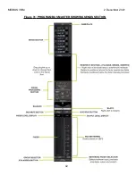
Indicators and controls are as follows:
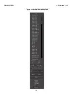
Monitor Selector
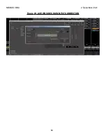
– this selects where the Monitor Strip is monitoring from. Monitoring
point can be set to anywhere in the VBM, as shown in
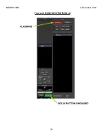
Solo Indicator/button
– this button flashes whenever there is an active solo as shown
. Click on the flashing button to clear the solo.
Isolated indicator/button
– this button is lit when a channel or bus strip is isolated from
soloing. Click on the button to de-isolate.
"Solo Isolate" is a mode which prevents a channel from muting when other channels are
solo'd. Ctrl-click (Cmd on a MAC) on a channel to solo-isolate it.
Pre Fader Listen
– Solo monitors pre the channel or bus fader
After Fader Listen
– Solo monitors post channel or bus fader
Exclusive Solo
– when engaged (and the indicator is lit) only one solo'd source will be
heard at a time. Normally all solo'd sources will be heard together.
Solo >> Mute
- when engaged, solo overrides mute. Muted sources will also be heard
in solo.
Redirect Section
– allows for insertion of signal processing plugins in the monitor path
Solo Boost
- this knob adds additional gain to a solo'd source. The button allows quick
presetting of the amount of boost to 3, 6 or 10 dB
DIM
- this knob sets the amount of monitor attenuation when the "
Dim
" button is
engaged. The button allows quick presetting of the amount of attenuation to -3, -6, -12
or -20 dB
L-R Controls
– These buttons allow mute, dim, solo or invert of the main left and right
monitor outputs
Mono
– sums left and right monitor paths to both outputs
Mute
– cuts all audio output from the monitor section
Monitor Attenuator
– this is the volume control for your monitoring speaker output.
The button allows quick presetting of the level to –3, -6, -12,-20 or –30 dB
52
Содержание Mixbus VBM
Страница 1: ...MANUAL VERSION 1 5 DATE 2 December 2021 NOTES For VBM 1 2 release ...
Страница 8: ...MIXBUS VBM 2 December 2021 Figure 2 VBM INPUT SECTION 8 ...
Страница 10: ...MIXBUS VBM 2 December 2021 Figure 3 VBM STEREO CHANNEL STRIP 10 ...
Страница 11: ...MIXBUS VBM 2 December 2021 Figure 4 VBM MONO CHANNEL STRIP 11 ...
Страница 18: ...MIXBUS VBM 2 December 2021 Figure 11 CHANNEL EXTERNAL SEND 18 ...
Страница 20: ...MIXBUS VBM 2 December 2021 Figure 12 SIGNAL PROCESSING ACCESS 20 ...
Страница 23: ...MIXBUS VBM 2 December 2021 Figure 14 PROGRAM BUS ASSIGN BUTTONS 23 ...
Страница 33: ...MIXBUS VBM 2 December 2021 Figure 24 VCA MASTER 33 ...
Страница 36: ...MIXBUS VBM 2 December 2021 Figure 27 VBM BUS MASTERS 36 ...
Страница 38: ...MIXBUS VBM 2 December 2021 Figure 28 PROGRAM BUS MASTER 38 ...
Страница 42: ...MIXBUS VBM 2 December 2021 Figure 31 PROGRAM BUS MASTER SHOWING SENDS SECTION 42 ...
Страница 47: ...MIXBUS VBM 2 December 2021 Figure 36 MIX MINUS BUS MASTER 47 ...
Страница 51: ...MIXBUS VBM 2 December 2021 Figure 38 VBM MONITOR STRIP 51 ...
Страница 53: ...MIXBUS VBM 2 December 2021 Figure 39 MONITOR SELECTOR 53 ...
Страница 54: ...MIXBUS VBM 2 December 2021 Figure 40 MONITOR STRIP IN SOLO 54 ...
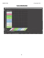
Страница 56: ...MIXBUS VBM 2 December 2021 Figure 42 ROUTING TOOL 56 ...
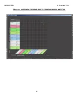
Страница 57: ...MIXBUS VBM 2 December 2021 Figure 43 SHOWING A PROGRAM BUS TO PROGRAM BUS CONNECTION 57 ...
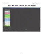
Страница 58: ...MIXBUS VBM 2 December 2021 Figure 44 MONITOR STRIP CONNECTION TO EXTERNAL INTERFACE 58 ...
Страница 62: ...MIXBUS VBM 2 December 2021 Figure 45 ACE IFB PLUGIN CONTROL PANEL Figure 46 ACE IFB PIN CONNECTIONS WINDOW 62 ...
Страница 64: ...MIXBUS VBM 2 December 2021 Figure 48 ACE IFB SIDECHAIN INPUT CONNECTION 64 ...
Страница 67: ...MIXBUS VBM 2 December 2021 Figure 50 ABOUT WINDOW END OF VBM USER MANUAL 67 ...


