background image

MIXBUS VBM

2 December 2021

Figure 


 2

  : VBM INPUT SECTION

8

Содержание Mixbus VBM

Страница 1: ...MANUAL VERSION 1 5 DATE 2 December 2021 NOTES For VBM 1 2 release ...

Страница 2: ... 2 2 11 Meter 28 2 2 12 Metering Point Select Button 28 2 2 13 Group Assign Button 29 2 2 14 VCA Assign Button 30 2 3 VCA MASTERS 32 2 4 BUSES 35 2 4 1 Program Buses 37 2 4 1 1 Program Bus Nameplate 39 2 4 1 2 Redirect Section 40 2 4 1 3 Program Bus Signal Processing 40 2 4 1 4 Lower Section 41 2 4 1 5 Sends Section 41 2 4 2 MixMinus Buses 46 2 4 2 1 Sends Section 48 2 4 2 2 Show Sends Button 48 2...

Страница 3: ...MIXBUS VBM 2 December 2021 7 0 APPENDIX 2 INSTALLATION AND LICENSING 65 7 1 GETTING STARTED 65 7 1 1 Installing The Software 65 7 1 2 Checking Licensing Status 66 3 ...

Страница 4: ...RE 20 GROUPING 29 FIGURE 21 CONTROL GROUPING OPTIONS 30 FIGURE 22 VCAS 31 FIGURE 23 CHANNEL ASSIGNMENT TO VCA MASTER 32 FIGURE 24 VCA MASTER 33 FIGURE 25 VCA MASTER NAME PLATE 34 FIGURE 26 MASTER MUTE FROM VCA MASTER 35 FIGURE 27 VBM BUS MASTERS 36 FIGURE 28 PROGRAM BUS MASTER 38 FIGURE 29 PROGRAM BUS NAMEPLATE 39 FIGURE 30 BUS SIGNAL PROCESSING 40 FIGURE 31 PROGRAM BUS MASTER SHOWING SENDS SECTIO...

Страница 5: ...MIXBUS VBM 2 December 2021 FIGURE 47 ACE IFB ADD SIDECHAIN INPUT 63 FIGURE 48 ACE IFB SIDECHAIN INPUT CONNECTION 64 FIGURE 49 ACCESSING VERSION AND LICENSING INFORMATION 66 FIGURE 50 ABOUT WINDOW 67 5 ...

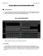
Страница 6: ...rison s Mixbus DAW platform Figure 1 VBM CONTROL PANEL Mixbus VBM runs on MAC Linux and Windows platforms 1 1 Premise Mixbus VBM is a computer based digital mixer for live broadcast mixing applications It is tailored to applications that require multiple mix minus feeds and can provide multiple program outputs It can be run locally or on a remote virtual server Audio inputs and outputs to VBM are ...

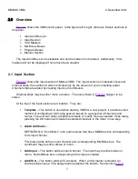
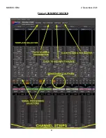
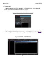
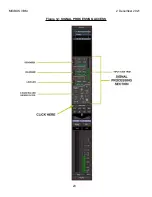
Страница 7: ...be stereo At the top of the input section are 4 buttons They are 1 Template This button is used when starting VBM for a new project It provides a fast method of configuring a full mixing session based on a preset list of channels and names The user can either accept the defaults or modify them as needed Once ready pressing the OK button will create the selected channels in the mixer in one step 2 ...

Страница 8: ...MIXBUS VBM 2 December 2021 Figure 2 VBM INPUT SECTION 8 ...

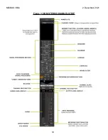
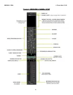
Страница 9: ...o or mono The channel strip in Figure 3 is a stereo channel strip The mono channel strip is shown in Figure 4 and is identical except for a pan control rather than a balance control see Section 2 2 6 and the level meter is a single meter rather than a pair of meters Features and functions of the channel strip are presented in the following sections 9 ...

Страница 10: ...MIXBUS VBM 2 December 2021 Figure 3 VBM STEREO CHANNEL STRIP 10 ...

Страница 11: ...MIXBUS VBM 2 December 2021 Figure 4 VBM MONO CHANNEL STRIP 11 ...

Страница 12: ... name plate provides for renaming changing colours and other controls Figure 5 CHANNEL NAME PLATE FUNCTIONS The Comments selection allows entry of notes or comments specific to this channel Once entered they may be read at any time by accessing this selection again as shown in Figure 6 Figure 6 CHANNEL COMMENT BOX 12 ...

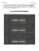
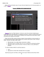
Страница 13: ...n and modified An example of this window is shown in Figure 7 and permits custom connections of the in and out ports to the plugins to be made addition and connection of sidechain inputs MIDI Controls where available and so on This option will not be shown if the channel has no plugins inserted Figure 7 PLUGIN PIN CONFIGURATION WINDOW 13 ...

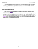
Страница 14: ... area allows addition of signal processing plugins inserts and external sends as shown in Figure 8 Signal flow in the channel strip is as depicted top to bottom in the redirect area The channel main fader is present by default The relative positions of the fader plugins and external sends may be rearranged simply by dragging the items up or down in the redirect area For example in Figure 8 the XT ...

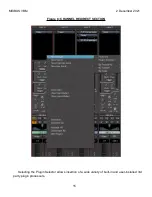
Страница 15: ...MIXBUS VBM 2 December 2021 Figure 8 CHANNEL REDIRECT SECTION Selecting the Plugin Selector allows insertion of a wide variety of built in and user installed 3rd party plugin processors 15 ...

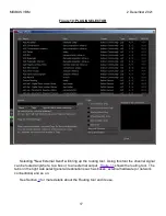
Страница 16: ... be inserted When there are large numbers of plugins installed it may be difficult to find the desired one The Plugin Selector provides a Search facility with a number of filter options to aid in finding a plugin As seen in the figure filters include filtering by type for example effects instruments or utilities filtering by format for example VST3 LV2 etc is provided by selecting the pulldown fil...

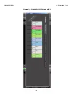
Страница 17: ...Using this tool the channel signal can be routed anywhere to a bus or to an external output Figure 11 shows the routing tool The tabs on the right side select general destinations such as buses external hardware or network connections and so on See Section 3 for more details about the Routing tool and its use 17 ...

Страница 18: ...MIXBUS VBM 2 December 2021 Figure 11 CHANNEL EXTERNAL SEND 18 ...

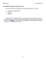
Страница 19: ... highpass filter leveler de esser de noiser Single clicking on the VBM Strip button above the program bus assign buttons opens the signal processing tools on all channel strips and output buses Signal processing on the channel strip is shown in Figure 12 The signal processing parameters may be modified by clicking and dragging on the buttons and knobs directly 19 ...

Страница 20: ...MIXBUS VBM 2 December 2021 Figure 12 SIGNAL PROCESSING ACCESS 20 ...

Страница 21: ...ter bar indicates the instantaneous amount of the de noising De esser The de esser has a range of 2dB to 18 dB attenuation adjusted by the Depth knob The Frequency knob adjusts the de essing corner frequency from 500 to 4 KHz The Ess button turns the processing on and off The slider at the left adjusts the de essing threshold The meter bar indicates the instantaneous amount of the de essing Levele...

Страница 22: ...bus strip see Section 2 4 1 5 Operation is slightly different between Contributors channels which have an associated MixMinus bus and regular inputs channels which do not On Contributor channels when a program bus is assigned but the fader is down off the button is circled in colour as shown in Figure 14 Whenever the fader is open the buttons will turn solid colour as shown in Figure 15 Regular in...

Страница 23: ...MIXBUS VBM 2 December 2021 Figure 14 PROGRAM BUS ASSIGN BUTTONS 23 ...

Страница 24: ... are also enabled When the fader is up signal also goes to all MixMinus buses of channels assigned to the same program bus EXCEPT the one corresponding to this input strip this is the minus function If no program buses are assigned bringing the fader up will NOT send signal to any MixMinus buses However signal will still go to any post fader external destinations that have been created 24 ...

Страница 25: ...ions are mutually exclusive with the program buses When the fader is down Lobby sends are active and program bus send is inactive as shown in Figure 16 When the fader is up Lobby sends are inactive and program sends are active as shown in Figure 17 Figure 16 LOBBY PROGRAM ACTIVENESS WITH FADER DOWN On normal non contributor input channels Lobby selections operate as an additional program bus signa...

Страница 26: ...wn and remains on those MixMinus buses assigned to the same program bus when the fader is up channels assigned to the same Lobby but different program buses will hear a channel s audio on their corresponding MixMinus buses only when that channel s fader is down When the channel fader is up audio from that channel to other channel s corresponding MixMinus buses not assigned to the same program buse...

Страница 27: ...mono signal is sent to bus left and bus right according to the position of the slider 2 2 7 Channel Slate The channel slate is a name plate the same as the name plate at the top of the channel Right clicking on the slate brings up the same options shown in Figure 5 2 2 8 Mute and Solo Buttons Engaging the Mute button mutes all outputs from the channel strip Engaging the Solo button solos the chann...

Страница 28: ...ng Point Select Button The metering point defaults to pre fader but can be changed via the meter source button as shown in Figure 18 Figure 18 METERING POINT SELECTOR Five metering point options are available Input the raw input to the channel strip before any processing Pre Fader the point immediately before the fader after any plugin processors Post Fader the point immediately after the fader Ou...

Страница 29: ...an be changed simply by dragging it up or down 2 2 13 Group Assign Button Grouping of input channels allows two or more channels to have their control functions such as fader and mute linked together For example grouped channels have all of their faders move together when the fader on one of the channels is grabbed and moved Grouping is created by clicking on the Group button as shown in Figure 20...

Страница 30: ...on When VCA masters exist the VCA button is present on all channels and bus masters and provides assignment to any VCA master Individual channels and bus masters may be assigned to more than one VCA master When VCA master assignment has been made the VCA button is replaced by buttons showing which VCA master is assigned Figure 22 shows an example Channel DDR2 is not assigned to any VCA master APB1...

Страница 31: ...es to VCA assignments as shown in Figure 23 VCA assignments or deassignments are made by clicking in the check boxes The Unassign All option simultaneously disconnects the channel or bus master from all VCA masters it is assigned to and does not appear when the channel is not assigned to any VCA master 31 ...

Страница 32: ...ed is unlimited Any input channel Program bus master or MixMinus bus master may be assigned to a VCA master The fader provides master level control of all assigned channels or buses with the amount of gain or attenuation displayed in the indicator window The Spill button reduces the control panel to display only those Input channels or MixMinus buses assigned to this VCA master However all 4 Progr...

Страница 33: ...MIXBUS VBM 2 December 2021 Figure 24 VCA MASTER 33 ...

Страница 34: ... control by selecting Drop Selected Channels Drop All Slaves disconnects ALL channels or bus masters assigned to the VCA master The M and P buttons are master mute and solo for all channels or bus masters assigned to this VCA master The P button will group solo all assigned channels or bus masters The M Button simultaneously mutes all channels or bus masters assigned to this VCA master In both cas...

Страница 35: ...R 2 4 Buses Figure 27 shows the VBM bus masters There are two types of buses Program buses MixMinus buses There are 4 Program buses available The number of MixMinus buses is variable corresponding to the number of Contributors created and following their naming 35 ...

Страница 36: ...MIXBUS VBM 2 December 2021 Figure 27 VBM BUS MASTERS 36 ...

Страница 37: ... 4 basic sections to the Program bus the Redirect Plugins section the signal processing section accessed by the VBM Strip button and the fader meter section at the bottom The 4th section the Sends section is not shown by default so is not shown in the figure and will be detailed in Section 2 4 1 5 37 ...

Страница 38: ...MIXBUS VBM 2 December 2021 Figure 28 PROGRAM BUS MASTER 38 ...

Страница 39: ...e options have the identical functions as for an Input strip as presented in Section 2 2 1 The additional option here is the Show Individual Gain Controls check box When selected the bus Sends section is displayed showing individual gain and pan controls and a signal active indicator The Sends section will be covered in Section 2 4 1 5 Figure 29 PROGRAM BUS NAMEPLATE 39 ...

Страница 40: ...igure 30 BUS SIGNAL PROCESSING The bus signal processing provided is as follows Leveler The Leveler is a compressor with a low fixed ratio and release time It is designed to gently smooth out the peaks in a wide range of signals The slider on the left adjusts the limiting threshold from 0 dB to 40 dB The Attack knob sets the attack time over a range of 4ms to 100 ms The Gain knob provides makeup g...

Страница 41: ... selector Metering point selector VCA assign button present if VCAs have been created Review Sections 2 2 7 through 2 2 14 for details on the operation of this section of the Program bus strip 2 4 1 5 Sends Section If the Show Individual Gain Controls box shown in Figure 29 is checked the Sends section will be displayed The Sends section provides additional level control and pan capabilities from ...

Страница 42: ...MIXBUS VBM 2 December 2021 Figure 31 PROGRAM BUS MASTER SHOWING SENDS SECTION 42 ...

Страница 43: ... Figure 32 PROGRAM BUS SENDS SECTION Figure 33 shows details of the Channel send controls The send from each input channel has the following gain trim this horizontal slider provides for gain trimming of the signal from the Input channel Gain is adjustable from fully OFF to 6 dB live audio indicator this is an indicator which will light up as shown whenever the fader on the Input or Contributor ch...

Страница 44: ...ent modes In Figure 34 note the position of the panner on input GVC F and on the GVC F send on program bus P2 The pan balance knob on P2 is gray in colour indicating it is linked to the panner on GVC F indicating 71 Left and 29 Right They will track when either one is adjusted Figure 34 BUS PANS LINKED 44 ...

Страница 45: ... set to 33 Left and 67 Right This capability can be used to individually set a channel s panning to each Program or MixMinus bus NOTE that the signals to be panned are derived PRE the panner on the channel strip Figure 35 BUS PANS UNLINKED The Sends section provides the capability to customize the mixes on each MixMinus and Program bus However these are advanced features and must be used with cons...

Страница 46: ...tion and the fader meter section at the bottom The 4 sections of the MixMinus bus master operate identically to those on the Program bus master with the exception of the automatic mix minus operation of the channel sends Unlike the Program bus masters the MixMinus bus masters have the Sends section displayed by default and the ACE IFB plugin is inserted by default See Appendix 1 in Section 6 for d...

Страница 47: ...MIXBUS VBM 2 December 2021 Figure 36 MIX MINUS BUS MASTER 47 ...

Страница 48: ...inus bus master for GVC A note that the send from GVC A is missing When Input Channels are assigned to Lobbies the audio flow is as described under Lobby operation in Section 2 2 5 1 2 4 2 2 Show Sends Button The Show Sends button enters a mode where level control of all Input and Contributor channels feeding this MixMinus bus will be controllable on their individual channel faders When selected o...

Страница 49: ...he Program Level slider controls the amount of Program level in the MixMinus output The signal originates on whatever Program bus the Contributor input channel is assigned to 2 4 2 5 Signal Processing Section Clicking on the VBM Strip button displays the signal processing sections on all input channel strips and buses The signal processing available on the MixMinus buses is identical to that on th...

Страница 50: ... 2 7 through 2 2 14 for details on the operation of this section of the MixMinus bus strip 2 5 Monitor Strip The VBM Monitor strip is shown in Figure 38 The monitor strip typically feeds the broadcast engineer s monitor speakers or headphones 50 ...

Страница 51: ...MIXBUS VBM 2 December 2021 Figure 38 VBM MONITOR STRIP 51 ...

Страница 52: ... when engaged and the indicator is lit only one solo d source will be heard at a time Normally all solo d sources will be heard together Solo Mute when engaged solo overrides mute Muted sources will also be heard in solo Redirect Section allows for insertion of signal processing plugins in the monitor path Solo Boost this knob adds additional gain to a solo d source The button allows quick presett...

Страница 53: ...MIXBUS VBM 2 December 2021 Figure 39 MONITOR SELECTOR 53 ...

Страница 54: ...MIXBUS VBM 2 December 2021 Figure 40 MONITOR STRIP IN SOLO 54 ...

Страница 55: ... vertical and destinations horizontal Clicking on a square in the matrix establishes an audio connection There are multiple tabs on both axes for selecting different groups of sources and destinations For example the figure shows VBM buses selected as both sources and destinations No connections are present However imagine you needed to feed the output of Program 1 into Program 4 for some reason B...

Страница 56: ...MIXBUS VBM 2 December 2021 Figure 42 ROUTING TOOL 56 ...

Страница 57: ...MIXBUS VBM 2 December 2021 Figure 43 SHOWING A PROGRAM BUS TO PROGRAM BUS CONNECTION 57 ...

Страница 58: ...MIXBUS VBM 2 December 2021 Figure 44 MONITOR STRIP CONNECTION TO EXTERNAL INTERFACE 58 ...

Страница 59: ... 4 0 Summary This document has presented an overview of the features of the Harrison Mixbus VBM virtual broadcast mixer This document will be refined and updated as additional features and capabilities are added to Mixbus VBM 59 ...

Страница 60: ...MIXBUS VBM 2 December 2021 5 0 References 1 Harrison Mixbus 32C v7 online manual 2 Harrison Mixbus 32C v6 online manual 60 ...

Страница 61: ...he plugin in the bus redirect section or by clicking on the pin connection button in the plugin control panel as shown in Figure 45 The pin connection window is shown in Figure 46 Note the 4 inputs at the top of the plugin of which 2 are the through audio paths and are automatically connected and 2 are sidechain inputs Thus the ducker function can be controlled from 2 different sources To add a si...

Страница 62: ...MIXBUS VBM 2 December 2021 Figure 45 ACE IFB PLUGIN CONTROL PANEL Figure 46 ACE IFB PIN CONNECTIONS WINDOW 62 ...

Страница 63: ...December 2021 Figure 47 ACE IFB ADD SIDECHAIN INPUT The actual sidechain connection is made by simply clicking on the sidechain source arrow on the right and dragging the connection to one of the sidechain inputs 63 ...

Страница 64: ...MIXBUS VBM 2 December 2021 Figure 48 ACE IFB SIDECHAIN INPUT CONNECTION 64 ...

Страница 65: ...up exe MAC The program is a dmg file such as MixbusVBM 1 1 112 dmg Linux The program is a tar tape archive file such as MixbusVBM 1 1 112 x86_64 gcc5 tar Install the program as you would install any other application on your computer 2 Install the license This is done by saving the attached license file to the home folder of the computer The home folder is the one that contains the Downloads and D...

Страница 66: ... the Programs and Monitor section 8 If you want to use NDI or other plugins you will need to have them installed on the system and then have MixbusVBM scan them From the Window menu open the Plugin Manager and then click the Re scan All button 9 For a quick test session click the template button on the top left and then click OK This will generate an NDI based setup with 2 contributor channels and...

Страница 67: ...MIXBUS VBM 2 December 2021 Figure 50 ABOUT WINDOW END OF VBM USER MANUAL 67 ...

Отзывы: