r01; n ,._.�
Positronrn�f"iiriff-[evelliiig ··--·· ·------
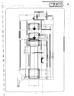
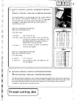
Locate the machine on a solid foundation allowing sufficient area for operation and maintenance
access (SEE GENERAL ARRANGEMENT AND FOUNDATION PLAN).
Although foundation bolt holes are provided for use where a fixed installation is considered
essential, for normal working it is not necessary to bolt the lathe to the floor.
The following levelling procedure is recommended:
Insert steel plates approximately 150mm x 150mm x 12mm thick under each (8) jacking point.
Level the machine using only two outer pafrs of jacking screws, at this stage erisuring that
the. two inner pairs of screws are retracted.
The two inner pairs of jacking screws should then be carefully screwed down, adjusting only
to a finger tight condition.
Electrical Supply
Over-current protection for the machine supply conductors is to be provided by user as follows
{preferably through a fused isolator sighted at the origin of the main ·supply cable):-
3 Phase Supply Voltage
Conductor Capacity
Over-Current Device
Under320V
40AMP MIN
60AMP MAX
Over320V
30AMP MIN
40AMP MAX
External wiring should be of a permanent character and oe undertaken by a competent electrician.
Bectrical entry is at the R.H. side of the control cabinet {looking from the rear of the machine)
and tapped '25m m electrical conduit'.
Line connections should be to isolator terminals and a substantial earth continuity conductor
must be connected to the earth tenninal on the panel (SEE ELECTRICAL WIRING DIAGRAM).
Motor direction must be CLOCKWISE looking on driving end, (SEE DIRECTION ARROW ON
MACHINE FRAME).
,
.
Lubrication
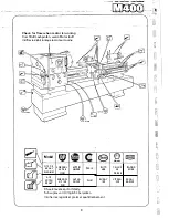
(REFER TO THE LUBRICATION DIAGRAM)
Lathes are normally despatched without lubricating oils.
Ensure that the headstock lubrication tank (mounted in the rear of the machine base at the
headstock end), gearbox and apron are filled to the level of their respective oil sight windows.
Operate the centralised slidway lubrication system by pulling and releasing the knob at the botto m
of the apron and oil the topslide dials and changewheel stud, ·etc. through the appropriate oil
nipples using the oil gun provided.
On starting the main motor check for evidence of oil flow at the headstock sight glass.
Running-in
For
optimum bearing life and performance it is recommended that high spindle speeds be avoided
during the initial life
of
the machine.
Alternatively
a
running-in procedure should be adopted as follows:-
Make a low feed rate selection and run the machine light for 3 hours at 500 r.p.m.
then for 2 hours at 800 r.p.m.
then for 1 hour at 1250 r.p.m.
then for
1/2
hour at 1600 r.p.m.
6
Содержание M400
Страница 1: ...420mm 16 1 2 heavy duty centre lathe Operations Manual info harrisonlathe com 800 575 2843 ...
Страница 6: ... t _ ___ 1n_s_t_a_lla_ t_io_n___ J 3 ...
Страница 9: ...l i I_ __ f1 fi r i l si 1 L 1 i i I i 1 1 1 I i I Ikl I I Iff1 wr i r1 J a i Lubrication 7 II J ...
Страница 11: ... t 1 p I _ u I il I r I f l l i l t J l t j ft t I J tr l i J I I r 9 I I I t 4 1 Operation J r ...
Страница 14: ... 2 I _ N I r 1 __ lilt n I I 1 II CJ t k J 29 1 Jit S fi IZ n I 28 i i i Ii ...
Страница 19: ...I i f n u 17 Thread cutting ...
Страница 25: ...i _1 L l fi l l b f_ _ _1 1 J 0 U C l 23 ____J Maintenance i I i ...
Страница 33: ...n td j t L f _J r i J Llf J I 7 r l LJ __ P_a_rt_s_ _s_e_c_ti_o_n __J ...
Страница 36: ... _ d i I O i I L l LJ 400 4 79 t M8x30 FV D001H2093 D272H1002 M16x75 FH r l M16 FN 35 V 401 1 ...
Страница 46: ...t 1 l 4 79 403 050 403 051 A03 058 SP 996 M12 1 L D4o t 45 SP996M12 j 03 053 403 3 ...
Страница 52: ...M8 Fl 1ETRIC J0 4 111 7 16 50 813 30 4 160 304 162 404 5 ...
Страница 66: ...M20 FH A 02O WN 411 028 1 411 025 4 11 026 411 14 64 J ...
Страница 67: ...r 1 r J M16x60 FJJ 411 013 65 411 012 411 010 411 011 411 16 ...
Страница 68: ...__ 411 052 66 411 050 41i Q53 411 31 i I J 1 t 1 I ...
Страница 71: ...C I J p t CJ 411 131 69 411 133 411 136 R A22 8 2RS INA g 411 135 411 100 M12 WN g M12x70 FD1 6 411 41 ...
Страница 74: ...411 200 411 202 M10 Fll 411 205 0401H0001 72 411 204 M10x35 FY 3 411 67 ...
Страница 76: ...M16 FH 413 035 ti 413 033 M6xl0 FXWl A 413 036 413 042 413 024 ll4x25 PT 413 00 4 PH006 413 005 413 l ll 74 ...
Страница 83: ... LJ l J t f 1 I i 1 i J r s 0 i _____ _II j 1 J J 9 8 9 0 5 i 1 1 l s s I r i ...


