•
_ :
--�rive Belts
(Fig.
1
anc! �) _:_ .. _
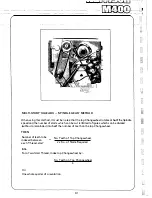
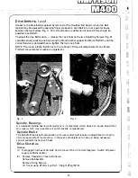
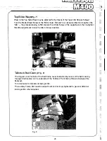
Access to the Drive Belts is gained by removal of the moulded End Guard, when Vee Belt
tension may be.assessed by applying finger pressure to each Belt in turn at a point midway
between the two Pulleys (Fig. 1). For correct tension a deflection of about 10mm should be
possible in each Belt.
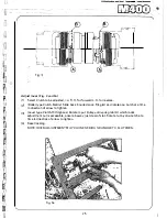
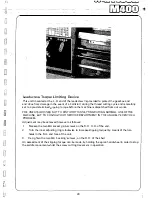
To adjust the Vee Belt tension - release the Lock Nuts on the two Adjusting Screws (Fig. 2)
and alternatively slacken one Screw and tighten the other against the Motor Platform until the·
correct tension is obtained then re-tighten the two Lock Nuts.
NOTE: The round 'elastic' Belt Drive to the Lubricant Pump will compensate for any Motor
Platform movement and needs no adjustment.
Fig. 1
Fig. 2
Spindle Bearings
A pre-loaded spindle bearing arrangement is incorporated which does not require adjustment.
Any wear which may take place is automatically compensated.
Spindle Brake
The Spindle Brake is self compensating for wear and should require no adjustment during the
normal use and life of the machine. In the event of adjustment or 'set-up' being necessary,
consult separate Instruction Sheet.
Drive Clutches
Access
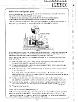
( 1) Disengage Clutches at Spindle Control Lever (24 on Controls Diagram). Switch off power
supply at Mains Isolator.
(2) Remove Headstock Cover as follows:
Remove Rubber Mat.
Remove Fixing Screws.
Lift Cover using 012mm Eye Bolt. (Weight 28kg ( 62 lb).
24
- ---- -L{'
--i
Содержание M400
Страница 1: ...420mm 16 1 2 heavy duty centre lathe Operations Manual info harrisonlathe com 800 575 2843 ...
Страница 6: ... t _ ___ 1n_s_t_a_lla_ t_io_n___ J 3 ...
Страница 9: ...l i I_ __ f1 fi r i l si 1 L 1 i i I i 1 1 1 I i I Ikl I I Iff1 wr i r1 J a i Lubrication 7 II J ...
Страница 11: ... t 1 p I _ u I il I r I f l l i l t J l t j ft t I J tr l i J I I r 9 I I I t 4 1 Operation J r ...
Страница 14: ... 2 I _ N I r 1 __ lilt n I I 1 II CJ t k J 29 1 Jit S fi IZ n I 28 i i i Ii ...
Страница 19: ...I i f n u 17 Thread cutting ...
Страница 25: ...i _1 L l fi l l b f_ _ _1 1 J 0 U C l 23 ____J Maintenance i I i ...
Страница 33: ...n td j t L f _J r i J Llf J I 7 r l LJ __ P_a_rt_s_ _s_e_c_ti_o_n __J ...
Страница 36: ... _ d i I O i I L l LJ 400 4 79 t M8x30 FV D001H2093 D272H1002 M16x75 FH r l M16 FN 35 V 401 1 ...
Страница 46: ...t 1 l 4 79 403 050 403 051 A03 058 SP 996 M12 1 L D4o t 45 SP996M12 j 03 053 403 3 ...
Страница 52: ...M8 Fl 1ETRIC J0 4 111 7 16 50 813 30 4 160 304 162 404 5 ...
Страница 66: ...M20 FH A 02O WN 411 028 1 411 025 4 11 026 411 14 64 J ...
Страница 67: ...r 1 r J M16x60 FJJ 411 013 65 411 012 411 010 411 011 411 16 ...
Страница 68: ...__ 411 052 66 411 050 41i Q53 411 31 i I J 1 t 1 I ...
Страница 71: ...C I J p t CJ 411 131 69 411 133 411 136 R A22 8 2RS INA g 411 135 411 100 M12 WN g M12x70 FD1 6 411 41 ...
Страница 74: ...411 200 411 202 M10 Fll 411 205 0401H0001 72 411 204 M10x35 FY 3 411 67 ...
Страница 76: ...M16 FH 413 035 ti 413 033 M6xl0 FXWl A 413 036 413 042 413 024 ll4x25 PT 413 00 4 PH006 413 005 413 l ll 74 ...
Страница 83: ... LJ l J t f 1 I i 1 i J r s 0 i _____ _II j 1 J J 9 8 9 0 5 i 1 1 l s s I r i ...

