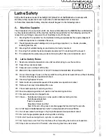
. ·- ·-·· . . .. .
··---�·
.. -·-·
-
.. ...
·-
,. ___ ... .
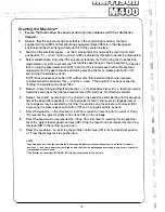
Starti"hg the Machine**
1.
Ensure
that
lubrication has been carried
out in
accordance with the Lubrication
diagram.
2.
Check
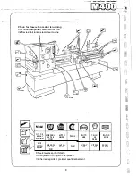
- tliat the spindle control lever (24) is in the central (stop) position, the feed
engagement lever (28) and threadcutting engagement lever (30) are in the disengaged
positions and that the changewheel guard is firmly secured in place.
3.
Switch on the electrical supply - at the mains isolator (4) and press the main motor start
pushbutton (7) - when 'motor running' will be indicat_ed by this button becoming illuminated.
4.
Select spindle speed {only when the spindle is stationary) by first turning the three position
range selector fever (6) to- present the appropriate s'peed range on the top segment of the dial,
then turning the speed selector dial {5) to.point to the required speed within this segment
(engagement of the gears may-be assisted by pressing the brake release pushbutton (10)
and turning the spindle by hand.
NOTE: Brake release pushbutton (10) will become illuminated and flash when pressed,
to indicate that the spindle is free - and may 'creep '. This condition may be cancelled by
'inching' the spindle conJrol lever (24).
5.
Select
-forward longitudinal feed direction - at the headstock lever (3) i.e. feeding towards
headstock and check that the feed reverse lever (29) 'matches' the direction selected.
6.
Select�
feed rate*, by referring to the charts on the headstock and selecting (in the sequence
listed) the appropriate positions on the feed selector dial (1) and levers (2) (engagement of
the feed gears may be assisted by 'inching' the spindle using the spindle control lever (24))
or pressing the brake release pushbutton (10) and turning the spindle by hand.
7.
Start
the spindle
- in the direction of rotation required by: lowering (for forward) or lifting
(for reverse) the 'gated' spindle control lever (24) on the carriage.
8.
Start the feed motion as required by: lifting (for cross feed) or lowering (for longitudinal
feed) the 'gated' feed e·ngagt:ment lever (28). Stop the feed motion as required by returning
this lever (28) to the central st<?P position. -
· ·
9.
Stop the
machine -
by returning the sp.indle control lever (24} to its central (stop) position
or: Press the emergency stop pushbutton.
NOTES
*Feed Selections from the Charts automatically disengage the leadscrew drive at the gearbox (i.e. by calling for selector
position X) - and for minimum wear ,the thread indicator dial should be disengaged by swinging the pinion out of mesh with
the leadscrew when not in use.
-see Installation Instructions (RUNNING-iNl if starting the machine for the firsftime.
14
Содержание M400
Страница 1: ...420mm 16 1 2 heavy duty centre lathe Operations Manual info harrisonlathe com 800 575 2843 ...
Страница 6: ... t _ ___ 1n_s_t_a_lla_ t_io_n___ J 3 ...
Страница 9: ...l i I_ __ f1 fi r i l si 1 L 1 i i I i 1 1 1 I i I Ikl I I Iff1 wr i r1 J a i Lubrication 7 II J ...
Страница 11: ... t 1 p I _ u I il I r I f l l i l t J l t j ft t I J tr l i J I I r 9 I I I t 4 1 Operation J r ...
Страница 14: ... 2 I _ N I r 1 __ lilt n I I 1 II CJ t k J 29 1 Jit S fi IZ n I 28 i i i Ii ...
Страница 19: ...I i f n u 17 Thread cutting ...
Страница 25: ...i _1 L l fi l l b f_ _ _1 1 J 0 U C l 23 ____J Maintenance i I i ...
Страница 33: ...n td j t L f _J r i J Llf J I 7 r l LJ __ P_a_rt_s_ _s_e_c_ti_o_n __J ...
Страница 36: ... _ d i I O i I L l LJ 400 4 79 t M8x30 FV D001H2093 D272H1002 M16x75 FH r l M16 FN 35 V 401 1 ...
Страница 46: ...t 1 l 4 79 403 050 403 051 A03 058 SP 996 M12 1 L D4o t 45 SP996M12 j 03 053 403 3 ...
Страница 52: ...M8 Fl 1ETRIC J0 4 111 7 16 50 813 30 4 160 304 162 404 5 ...
Страница 66: ...M20 FH A 02O WN 411 028 1 411 025 4 11 026 411 14 64 J ...
Страница 67: ...r 1 r J M16x60 FJJ 411 013 65 411 012 411 010 411 011 411 16 ...
Страница 68: ...__ 411 052 66 411 050 41i Q53 411 31 i I J 1 t 1 I ...
Страница 71: ...C I J p t CJ 411 131 69 411 133 411 136 R A22 8 2RS INA g 411 135 411 100 M12 WN g M12x70 FD1 6 411 41 ...
Страница 74: ...411 200 411 202 M10 Fll 411 205 0401H0001 72 411 204 M10x35 FY 3 411 67 ...
Страница 76: ...M16 FH 413 035 ti 413 033 M6xl0 FXWl A 413 036 413 042 413 024 ll4x25 PT 413 00 4 PH006 413 005 413 l ll 74 ...
Страница 83: ... LJ l J t f 1 I i 1 i J r s 0 i _____ _II j 1 J J 9 8 9 0 5 i 1 1 l s s I r i ...


