r
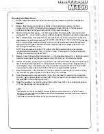
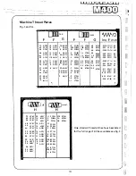
(A) METRIC THREADS on METH.IC LEADSCREW MACHiNES
or
ENGLISH THREADS on ENGLISH LEADSCREW MACHINES
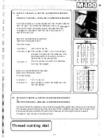
For these threads it is recommended that the "thread indicator
dial" be used·- this allows the leadscrew nuts to be disengaged
at the end of each screwc;utti ng pass, provided that the\.
re-engaged in accordance with the chart mounted on +h,
face of the dial unit.
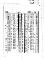
METRIC LEADSCREW MACHINES
(METRIC THREADS ONLY)
The chart shows: -
in column 1.
mm pitch to be cut.
in column 2. (•l The number of teeth in the 'pick-off gear'
arranged to mesh with the leadscrew, (this
being selected from the stack, stored on
the bottom of the dial spindle).
in column 3.
The dial numbers at which the leadscrew
nuts may be engaged.
ENGLISH LEADSCREW MACHINES
(ENGLISH TH READS ONLY}
The chart shows: -
in column 1.
in column 2.
T.P.I. to _be cut.
Dial numbers at which the leadscrew nuts
may be engaged.
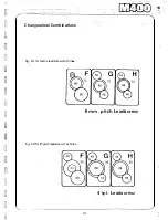
(B) ENGLISH THREADS on METRIC LEADSCREW MACHINES
or
METRIC THREADS on ENGLI SH LEADSCREW MACHINES
�---�-....._.....�-
Ollll)mm
•
·225
18 15
4
16 1-8
25
16 1-8
4-5
18 15
.75 16 1-8
5
20 1357
1
16 1-8
5·5
22 15
1·25 20 1357
6
16 1-8
16 1-8
7
14 15
Hi'
16 1357
8
16 1357
1 ·75 14 15
9
18 15
2
16 1-8
10
20 1357
2·5
20 1357
1l
22 15
16 1-8
12
16 H
H
14 15
14
14 15
812
[lIIIDins
2 1-8
8
1-8 22 1-8
2½ l 5
9
1357
24
1-8
2! !
10
1-8
26
. l -8
3
1357 l1 1357 27 13S 7
3¼ l
114 15
28
J .. g
Jl 15
12 1-8
JO
1-8
4 1-8
13
1357 32 1-8
4; 15
14.
1-8
36
1-8
1357
16
!-8
40
1-8
6
1-8
18
1-8
44
1-8
7 1357
19
1357
48
1-8
7} 15
20
1.--8
56
1-8
813
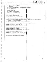
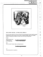
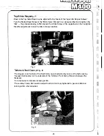
For these threads the leadscrew nuts are kept engaged throughdut the cutting of any one thread.
This involves reversing the whole drive by means of the 'spindle control lever' (24) at each end of
the screwcutting pass whilst at the.same time relieving or increasing the cut as required.
(Threads 'A' may also be cut by this method).
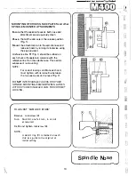
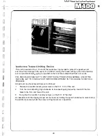
Thread-cutting dial
21
Содержание M400
Страница 1: ...420mm 16 1 2 heavy duty centre lathe Operations Manual info harrisonlathe com 800 575 2843 ...
Страница 6: ... t _ ___ 1n_s_t_a_lla_ t_io_n___ J 3 ...
Страница 9: ...l i I_ __ f1 fi r i l si 1 L 1 i i I i 1 1 1 I i I Ikl I I Iff1 wr i r1 J a i Lubrication 7 II J ...
Страница 11: ... t 1 p I _ u I il I r I f l l i l t J l t j ft t I J tr l i J I I r 9 I I I t 4 1 Operation J r ...
Страница 14: ... 2 I _ N I r 1 __ lilt n I I 1 II CJ t k J 29 1 Jit S fi IZ n I 28 i i i Ii ...
Страница 19: ...I i f n u 17 Thread cutting ...
Страница 25: ...i _1 L l fi l l b f_ _ _1 1 J 0 U C l 23 ____J Maintenance i I i ...
Страница 33: ...n td j t L f _J r i J Llf J I 7 r l LJ __ P_a_rt_s_ _s_e_c_ti_o_n __J ...
Страница 36: ... _ d i I O i I L l LJ 400 4 79 t M8x30 FV D001H2093 D272H1002 M16x75 FH r l M16 FN 35 V 401 1 ...
Страница 46: ...t 1 l 4 79 403 050 403 051 A03 058 SP 996 M12 1 L D4o t 45 SP996M12 j 03 053 403 3 ...
Страница 52: ...M8 Fl 1ETRIC J0 4 111 7 16 50 813 30 4 160 304 162 404 5 ...
Страница 66: ...M20 FH A 02O WN 411 028 1 411 025 4 11 026 411 14 64 J ...
Страница 67: ...r 1 r J M16x60 FJJ 411 013 65 411 012 411 010 411 011 411 16 ...
Страница 68: ...__ 411 052 66 411 050 41i Q53 411 31 i I J 1 t 1 I ...
Страница 71: ...C I J p t CJ 411 131 69 411 133 411 136 R A22 8 2RS INA g 411 135 411 100 M12 WN g M12x70 FD1 6 411 41 ...
Страница 74: ...411 200 411 202 M10 Fll 411 205 0401H0001 72 411 204 M10x35 FY 3 411 67 ...
Страница 76: ...M16 FH 413 035 ti 413 033 M6xl0 FXWl A 413 036 413 042 413 024 ll4x25 PT 413 00 4 PH006 413 005 413 l ll 74 ...
Страница 83: ... LJ l J t f 1 I i 1 i J r s 0 i _____ _II j 1 J J 9 8 9 0 5 i 1 1 l s s I r i ...

