manualshive.com logo in svg
background image

17FEB2021  |  630-00113 REV C

HIGHLANDER II

VERTICAL 

PLATFORM LIFT

INSTALLATION &

SERVICE MANUAL

Содержание HIGHLANDER II

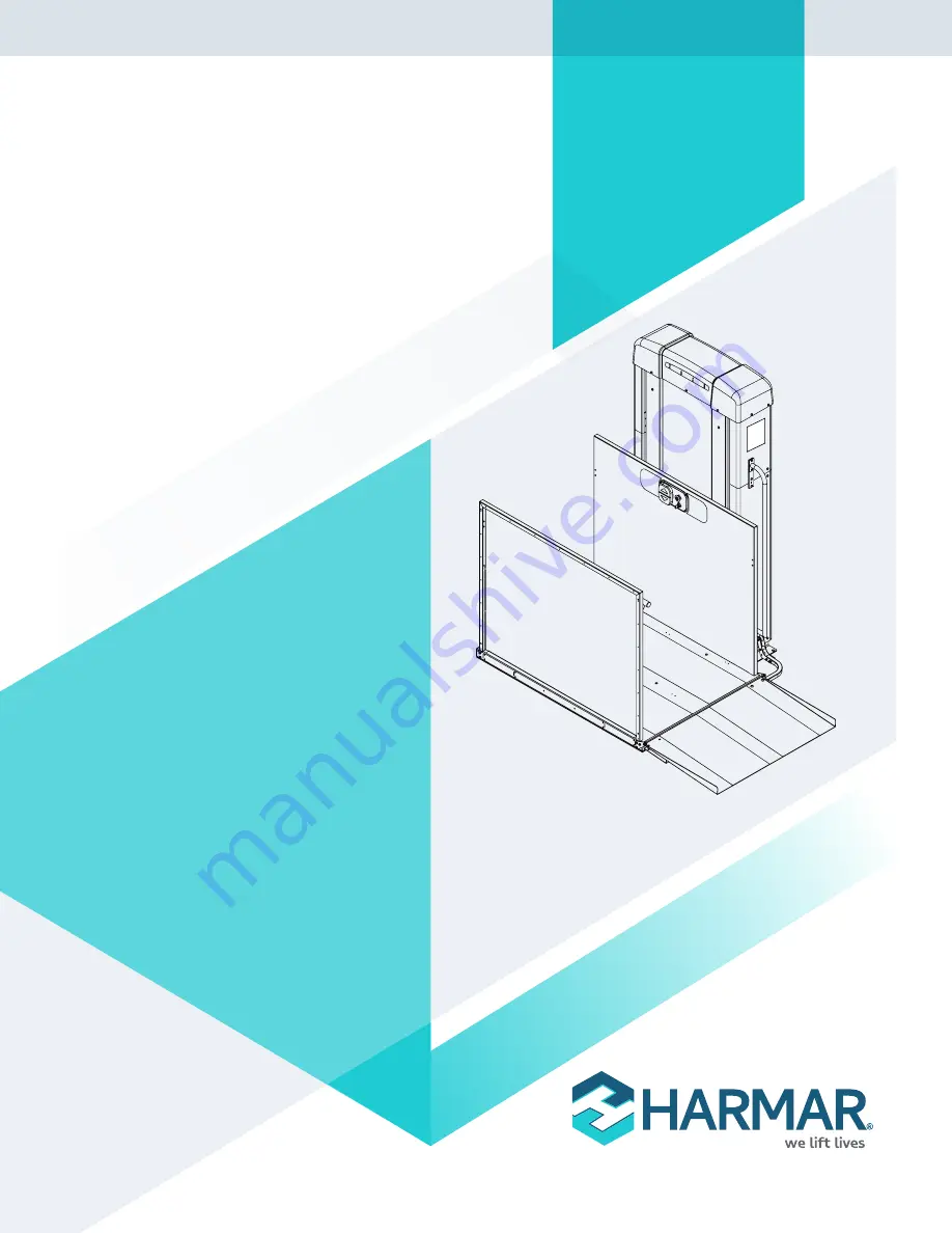
Страница 1: ...17FEB2021 630 00113 REV C HIGHLANDER II VERTICAL PLATFORM LIFT INSTALLATION SERVICE MANUAL...

Страница 2: ......

Страница 3: ...ay No Floor Penetration 12 Electrical Connection 12 Battery Backup 13 Platform Connection 14 Installing the Platform Control Guard Panel 14 Installing a Platform Gate If Equipped 14 Installing the Pla...

Страница 4: ...conditions that jeopardize the technician s safety or ability to complete the installation in a safe manner Tents canopies or other outdoor provisions that help protect the work area from weather or...

Страница 5: ...ns on the particular lift model and configuration CODE STATEMENT The Harmar Highlander II lift has been designed to meet ASME A18 1 Safety Standard for Platform Lifts and Stairway Chairlifts under sec...

Страница 6: ...r must comply with 2 1 1 and with the building code NOTE There are 3 different sections of rules for a commercial application 2 1 1 Runway Enclosure Provided 2 1 2 Partial Runway Enclosure Provided 2...

Страница 7: ...HIGHLANDER II SECTION 2 KEY VERTICAL PLATFORM LIFT ELEMENTS 1 Top Cap 2 Lift Status Indicator Lights 3 Data Serial Tag 4 Platform 5 Platform Side Panel 6 Grab Rail if supplied 7 Platform Controls 8 P...

Страница 8: ...ew 4 Batteries if supplied 5 Battery Charger and assembly tray if supplied not shown 6 Inverter if supplied 7 Control Electronics Assembly 8 Upper Lower Lower Final Limit Switches 9 Tower Frame 10 Tow...

Страница 9: ...p Square Level Multimeter Wire Cutters Wire Puller Stripper Crimping Tool Hammer Drill 3 8 Wrench Set 7 16 1 2 9 16 3 4 Allen Wrench 1 8 3 16 5 16 Torx Wrench T20 No 1 Phillips Head Screwdriver No 2 F...

Страница 10: ...cated Electrical Lead per local code UNLOADING The 4 VPL is shipped standing up shrink wrapped to a pallet The pallet dimensions are 48 x 48 x 83 Units are screwed into the pallet installers will requ...

Страница 11: ...Care should be taken not to scratch or damage panels when removing carrying and reinstalling them Special care must be taken to protect any landscaping or flooring surfaces that might be damaged by t...

Страница 12: ...should only be lifted by the rectangular tubes below the top plate ELECTRICAL CONNECTION 1 Remove and discard the temporary bolt and nut 9 16 hex that secures the tensioning pulley to the carriage fo...

Страница 13: ...d route down through the back of the center wire channel to the bottom of the lift and out to a temporary 120V AC outlet See Figure 4 5 Junction box Back brace of tower Wire channel Figure 4 5 5 Once...

Страница 14: ...ntrol side guard panel posts into the pockets on the platform with the smooth side facing the inside of the platform Fasten in place with four 4 1 4 20 x 2 bolts Torque bolts down sufficiently to hold...

Страница 15: ...he guard panel post and thread into the platform NOTE If a platform gate is equipped the pivot tabs mount to the face of the gate with different hardware and nuts 2 Assemble the ramp roller arm into t...

Страница 16: ...wiring to a landing gate See Figure 4 11 for wiring to a call station and strike Figure 4 9 Figure 4 10 Figure 4 11 NOTE If the call send switch is installed in the gate the wires are routed between...

Страница 17: ...when the wiring is corrected NOTICE 10 Reinstall interlock gate post covers and hole plugs NOTE Gates are field reversible contact Harmar Technical Service for instructions FASCIA PANEL INSTALLATION...

Страница 18: ...gang outlet box 1 Remove four 4 label plate screws and label plate See Figure 4 15 Back Cover Front Cover 4 Cover Screws Label Plate Key Lock optional Figure 4 15 2 Remove four 4 cover screws and the...

Страница 19: ...ls please refer to the supplemental guide Highlander II Wiring Schematics NOTE A wiring diagram with part number 640 00025 is placed in a packet with your shipment NOTE Von Duprin strikes are not comp...

Страница 20: ...Apply temporary power and verify all four 4 LED indicator lights on the control board are solid green Manually depress the final limit switch the highest positioned switch and verify any travel of pla...

Страница 21: ...t the top cap Reconnect the power to the lift OPERATIONAL CHECK Upon installation and at scheduled intervals the operation of the VPL must be verified NOTE ASME A18 1 2017 requires that when the lift...

Страница 22: ...15 Amp breaker The fuses should be a minimum of 15A See Figure 4 18 OUTSIDE TOWER CONDUIT DPST FUSED DISCONNECT G G N L S L INSIDE TOWER JUNCTION BOX 5X WIRE NUTS Figure 4 18 Route wiring from disconn...

Страница 23: ...ications this would take place with any or all of the following the property owner facilities manager or any personnel who may oversee the unit s use or control its access PROVIDE OVERVIEW Review all...

Страница 24: ...se 2 x4 beneath platform base when connecting to carriage INSTALL LANDING GATE Screw to Landing Pre run Wiring INSTALL FASCIA PANEL Attach to Open Areas Under Gate Ensure Smooth Flush No Gaps Protrusi...

Страница 25: ...flashing light STATUS LED STATUS 1 2 3 4 All OFF Lift will not function Major Fault No Power and no battery or Low Power Mode Service is Required Any Green or Green Lift functional No faults Green Gr...

Страница 26: ...Amber Motor is drawing too much current Platform will only go down Service is required Amber Amber Safety pan has been triggered Platform will only go up Amber Float switch has been triggered Platfor...

Страница 27: ...d Lift out of service Final limit switch is triggered Service is required Red Lift out of service Top landing switch did not change state when platform should have moved off landing Service is require...

Страница 28: ...ONICS If the Indicator LEDs do not provide enough information to fully troubleshoot a potential issue it may be necessary to access the control electronics below the top cap of the tower Access the co...

Страница 29: ...outputs on the Control Board See Figure 6 3 Figure 6 3 Indicator Board Connector Alarm Connector 3A Circuit Breaker Screw Terminal Motor Thermocouple Connector Brake Connector Down Contactor Connector...

Страница 30: ...Indicator LEDs 26X Green Circuit Status LEDs 3 3V Power LEDs 24V Power LEDs DESCRIPTION COLORS STATUS TROUBLESHOOTING 4X Indicators Green Amber Red These LEDs exactly duplicate the Indicator LEDs on T...

Страница 31: ...en LED ON indicates the Up button in the Bottom Call Station is being depressed Down Bottom Green LED ON indicates the Down button in the Bottom Call Station is being depressed Bottom Gate Green LED O...

Страница 32: ...re 11 safety pan switches in platform Bottom Land Green LED ON indicates the Bottom Landing switch is closed The switch should be closed only when platform is at that landing Float Switch Green LED ON...

Страница 33: ...check brake operation and is recommended to be used in the emergency lowering procedure RESET MOMENTARY SWITCH Pressing the RESET momentary switch will reset the processor and exit Service Mode if boa...

Страница 34: ...cs to change based on configuration If needed these jumpers are cut in the factory and should never need to change 3 STOP JUMPER This jumper is cut in the factory on 3 stop lifts The control board wil...

Страница 35: ...tor is engaged after the motor comes to a stop If the platform is taking too long to come to a stop there could be an issue with this resistor or the wiring on it LOAD RESISTORS The load resistors fun...

Страница 36: ...urn to a full charge BATTERY CHECK RELAY Since we cannot check battery voltage while the battery is charging we have a Battery Check Relay that switches between charging and voltage monitoring The bat...

Страница 37: ...they should follow the Emergency Lowering Procedure to evacuate the occupant EMERGENCY LOWERING PROCEDURE In the event that the lift becomes disabled with passengers on the platform that is not at a...

Страница 38: ...atform from drifting with heavy loads Lowering the platform with the brake engaged will require a bit of strength typically the equivalent of being able to lift 20 lb with one arm 6 If the lift has po...

Страница 39: ...the built in safety device designed to detect obstructions under the platform and stop platform downward motion If there is an easy to remove obstruction please remove it If for any reason the safety...

Страница 40: ...t and legible If any safety or warning labels need to be replaced please contact your dealer Make sure you have a copy of the Owner s Manual A digital copy of the Owner s Manual is available at harmar...

Страница 41: ...HIGHLANDER II VERTICAL PLATFORM LIFTS Install Manual 17FEB2021 630 00113 REV C 41 NOTES HIGHLANDER II...

Страница 42: ...HIGHLANDER II VERTICAL PLATFORM LIFTS Install Manual 17FEB2021 630 00113 REV C 42 NOTES HIGHLANDER II...

Страница 43: ...HIGHLANDER II VERTICAL PLATFORM LIFTS Install Manual 17FEB2021 630 00113 REV C 43 NOTES HIGHLANDER II...

Страница 44: ...2075 47th Street Sarasota FL 34234 800 833 0478 harmar com...

Отзывы: