background image

Installing Wall-Mount (MXD) Panels

42

Modero X® Series Touch Panels - Installation & Hardware Reference Manual

Installing Wall-Mount (MXD) Panels

A Note About Wall and Rack Installation

Some products are installed in areas of differing temperature and cooling methodologies. These include products installed in walls, 

racks, cabinets, etc. Those areas may have different temperatures and/or cooling approaches that must be taken into consideration 

to maintain the product within the specified operating temperature.
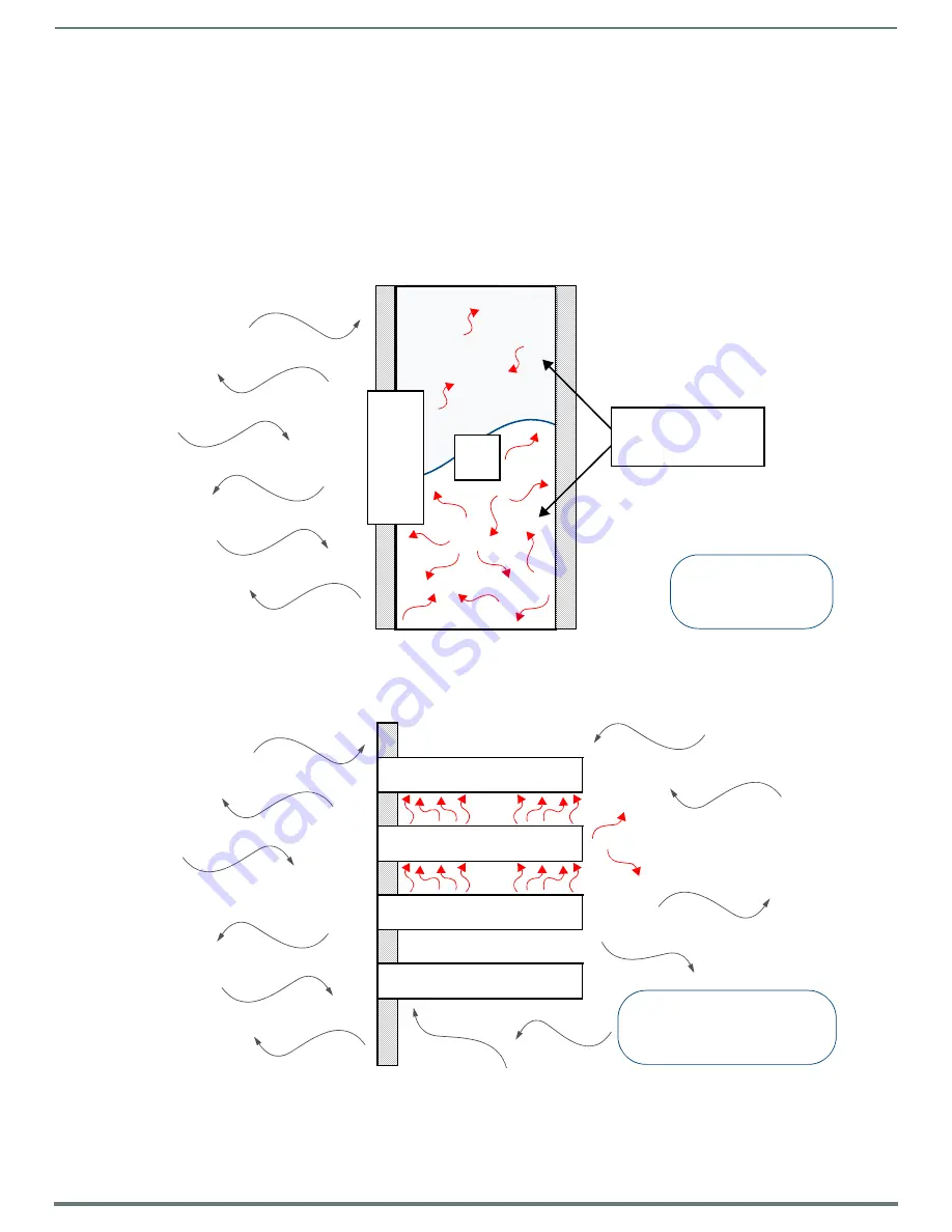
FIG. 21 shows an AMX device installed in a wall with a filled volume (such as with insulation or concrete), as well as with a closed 

volume (such as between studs in an otherwise finished wall). The diagram shows how heat generated by the device or other 

devices may have no way to escape, and may build up to levels that may affect device operation.

In FIG. 22, the diagram displays an AMX device in a typical rack mounting, with full air circulation around the front and back of the 

device. In this case, the main concern is with heat building up between components, possibly to levels that may affect device 

operation.

FIG. 21  

Heat convection in filled or closed volume, limited or no convection

FIG. 22  

Heat convection in rack-mounted devices

AMX DEV

IC

E

T2

T1

FILLED OR CLOSED

VOLUME, LIMITED OR

NO CONVECTION

T1, T2 < TOpMax

T1, T2 > TOpMin

T1

AMX DEVICE

T3

T4

T2

RACK MOUNTED DEVICES

T1, T2, T3, T4 < TOpMax

T1, T2, T3, T4 > TOpMin

Содержание MODERO X Series

Страница 1: ...MXD 1900L PAN P 19 4 MODERO X SERIES PORTRAIT WALL MOUNT TOUCH PANEL MXD 1900L PAN L 19 4 MODERO X SERIES LANDSCAPE WALL MOUNT TOUCH PANEL MXT 1000 10 1 MODERO X SERIES TABLETOP TOUCH PANEL MXD 1000...

Страница 2: ...es and the point where they exit from the apparatus 11 ONLY USE attachments accessories specified by the manufacturer 12 USE ONLY with a cart stand tripod bracket or table specified by the manufacture...

Страница 3: ...FORMATION The term IC before the radio certification number only signifies that Industry Canada technical specifications were met Le terme IC avant le num ro de certification radio signifie seulement...

Страница 4: ...INFORMATION This appliance is labeled in accordance with European Directive 2012 19 EU concerning waste of electrical and electronic equipment WEEE This label indicates that this product should not b...

Страница 5: ...Series Panels 13 MXT 2000XL PAN Tabletop 13 MXT 2000XL PAN Specifications 13 MXD 2000XL PAN Wall Mount Landscape Portrait 15 MXD 2000XL PAN Specifications 15 MXT D 1900L PAN 19 4 X Series Panels 19 M...

Страница 6: ...l 43 MXD 2000XL PAN Dimensions 44 MXD 1900L PAN Dimensions 45 Installing the Backbox 46 MXD 2000XL PAN Installation Dimensions 46 MXD 1900L PAN Installation Dimensions 47 Power via 13 5V 50 Wiring a 1...

Страница 7: ...ve 67 Transfer the Firmware File From the Flash Drive to the Touch Panel 68 Upgrading from Previous Firmware 68 Returning to Factory Default Firmware 69 Upgrading Firmware via NetLinx Studio 69 Transf...

Страница 8: ...Modero X Series Touch Panels Name FG Description Page Ref MXT 2000XL PAN FG5968 01 20 3 Modero X Series Panoramic Tabletop page 13 MXD 2000XL PAN P MXD 2000XL PAN L Portrait FG5968 05 Landscape FG596...

Страница 9: ...X Series No Comm Panels The X Series No Comm Panels do not have camera microphone NFC or Bluetooth capability Otherwise they have all of the functionality of the standard Modero X Series panels MXT 20...

Страница 10: ...nload at www amx com Bluetooth Support X Series G4 panels allow the use of Bluetooth keyboard and mouse combinations using HID Profile v1 1 Using a keyboard and mouse with the device requires use of t...

Страница 11: ...display page NOTE The maximum source resolution for Picture View is 1920x1920 pixels The maximum displayed resolution is the same as the screen resolution Starting Picture View 1 Connect a USB drive t...

Страница 12: ...View Send Command PIC The PIC Send Command stops either mode of Picture View or starts Preview Mode For more information please refer to the Modero X S Series G4 Touch Panels Programming Guide availa...

Страница 13: ...oenix 13 5V FG423 45 MXA MPL Modero X S Series Multi Preview Live FG5968 10 MXA MP Modero X S Series Multi Preview FG5968 20 CERTIFICATIONS FCC Part 15 Class B CE EN 55022 CE EN 55024 CE EN 60950 1 IE...

Страница 14: ...panel and video chat AUDIO Microphone 42 dB 3 dB sensitivity FET microphone Speakers 4 ohm 2 Watt 300 Hz cutoff frequency Supported Audio Codecs MP2 Layer I and II MP3 8 kHz 11 025 kHz 12 kHz 16 kHz 2...

Страница 15: ...5968 64 MXA MP Modero X S Series Multi Preview FG5968 20 MXA MPL Modero X S Series Multi Preview Live FG5968 10 PSN4 4 Power Supply 4 4 A 3 5 mm Phoenix 13 5V FG423 45 HPG 10 10K 3 4 Mini Grommet 10 P...

Страница 16: ...o Landscape 12 5 Portrait 5 12 Brightness 250 cd m2 Contrast Ratio 1000 1 Color Depth 16 7M colors Illumination LED Touch Overlay Projected capacitive multi touch support 3 simultaneous max VIEWING AN...

Страница 17: ...e for G 711 Voice 20ms Audio Output USB Audio out Micro USB port head hand set support File Formats WAV MP3 as part of touch panel file only no USB storage Intercom Full Duplex VoIP SIP v2 0 supported...

Страница 18: ...MXA RMK 20 Modero X Series Rack Mount Kit FG5969 60 MXA FMK 20 Flush Mount Kit for 20 3 Modero X Series Wall Mount Touch Panels FG5968 68 MXA MP Modero X S Series Multi Preview FG5968 20 MXA MPL Moder...

Страница 19: ...G5968 10 MXA MP Modero X S Series Multi Preview FG5968 20 CERTIFICATIONS FCC Part 15 Class B CE EN 55022 CE EN 55024 CE EN 60950 1 IEC 60950 1 C Tick CISPR 22 Class B IC UL 60950 1 RoHS WEEE compliant...

Страница 20: ...MP2 Layer I and II MP3 8 kHz 11 025 kHz 12 kHz 16 kHz 22 05 kHz 24 kHz 32 kHz 44 1 kHz 48 kHz AAC LC 8 kHz 96 kHz G 711 with Law VoIP encode decode at 8 kHz Suggested max packet size for G 711 Voice 2...

Страница 21: ...oth USB Adapter for Modero X S Series FG5968 19 MXA CLK Modero X S Series Cleaning Kit FG5968 16 MXA USB C USB Port Covers for the Modero X S Series Touch Panels FG5968 18 MXA HST Bluetooth Handset fo...

Страница 22: ...verlay Projected capacitive multi touch support 3 simultaneous max VIEWING ANGLE Vertical 89 Horizontal 89 MEMORY SDRAM 512 MB Flash 4 GB Maximum Project Size 2 4 GB flash available to user COMMUNICAT...

Страница 23: ...size for G 711 Voice 20ms Audio Output USB Audio out Micro USB port head hand set support File Formats WAV MP3 as part of touch panel file only no USB storage Intercom Full Duplex VoIP SIP v2 0 suppo...

Страница 24: ...CESSORIES MXA FMK 19 Flush Mount Kit 19 4 Modero X Wall Mount FG5968 69 MXA RMK 19 Modero X Series Rack Mount Kit FG5969 61 MXA MP Modero X S Series Multi Preview FG5968 20 MXA MPL Modero X S Series M...

Страница 25: ...G423 83 NXA ENET8 2POE Gigabit PoE Ethernet Switch FG2178 63 CERTIFICATIONS UL 60950 1 FCC Part 15 Class B C Tick CISPR 22 Class B CE EN 55022 EN 55024 and EN 60950 1 IEC 60950 1 IC IEC EN 60950 RoHS...

Страница 26: ...tt 300 Hz cutoff frequency Supported Audio Codecs MP2 Layer I and II MP3 8 kHz 11 025 kHz 12 kHz 16 kHz 22 05 kHz 24 kHz 32 kHz 44 1 kHz 48 kHz AAC LC 8 kHz 96 kHz G 711 with Law VoIP encode decode at...

Страница 27: ...F Compliant FG423 83 HPG 10 10K 3 4 Mini Grommet 10 Pack FG570 01 10K MXA BT Bluetooth USB Adapter for Modero X S Series FG5968 19 MXA CLK Modero X S Series Cleaning Kit FG5968 16 NXA ENET8 2POE Gigab...

Страница 28: ...jected capacitive multi touch support 3 simultaneous max VIEWING ANGLE Vertical 89 Horizontal 89 MEMORY SDRAM 512 MB Flash 4 GB Maximum Project Size 2 4 GB flash available to user COMMUNICATIONS Ether...

Страница 29: ...max packet size for G 711 Voice 20ms Audio Output USB Audio out USB port head hand set support File Formats WAV MP3 as part of touch panel file only no USB storage Intercom Full Duplex VoIP SIP v2 0...

Страница 30: ...letter boxing around the video in some cases MXD 1000 Specifications Cont OPTIONAL ACCESSORIES MXA FMK 10 Flush Mount Kit 10 Modero X Wall Mount FG5969 62 MXA RMK 10 Modero X Series Rack Mount Kit FG5...

Страница 31: ...et Switch FG2178 63 CERTIFICATIONS UL 60950 1 FCC Part 15 Class B C Tick CISPR 22 Class B CE EN 55022 EN 55024 and EN 60950 1 IEC 60950 1 IC IEC EN 60950 RoHS WEEE compliant TOUCH SCREEN DISPLAY Displ...

Страница 32: ...orage Intercom Full Duplex VoIP SIP v2 0 supported with AMX CSG GRAPHICS ENGINE AMX G4 G4 enhanced feature set supporting multi touch and gestures scrolling transitions See TPD4 Operations Guide for m...

Страница 33: ...G5968 08 Landscape MXD 700 L FG5968 14 FIG 13 MXD 700 Wall Mount Portrait and Landscape MXD 700 Specifications DIMENSIONS HWD Landscape 4 13 16 x 7 5 16 x 2 1 2 122 mm x 186 mm x 63 mm Portrait 7 5 16...

Страница 34: ...ISO IEC 14443B Unique Identifier UID typ range 25 max 5 Bluetooth Mouse Keyboard HID Profile v1 1 requires MXA BT Bluetooth Adapter FG5968 19 Handset Hands Free Profile v1 5 Headset Profile v1 2 requ...

Страница 35: ...A ports Power PoE Power over Ethernet 802 3af class 3 ENVIRONMENTAL Temperature Operating 32 F to 104 F 0 C to 40 C Temperature Storage 4 F to 140 F 20 C to 60 C Humidity Operating 20 to 85 RH Humidi...

Страница 36: ...r 802 3AF Compliant FG423 83 NXA ENET8 2POE Gigabit PoE Ethernet Switch FG2178 63 CERTIFICATIONS UL 60950 1 FCC Part 15 Class B C Tick CISPR 22 Class B CE EN 55022 EN 55024 and EN 60950 1 IEC 60950 1...

Страница 37: ...code decode at 8 kHz Suggested max packet size for G 711 Voice 20ms Audio Output USB Audio out USB port head hand set support File Formats WAV MP3 as part of touch panel file only no USB storage Inter...

Страница 38: ...ti Preview FG5968 20 MXA MPL Modero X S Series Multi Preview Live FG5968 10 PS POE AF TC PoE Injector 802 3AF Compliant FG423 83 CB MXP43 Rough In Box FG039 19 MXA BT Bluetooth USB Adapter for Modero...

Страница 39: ...vice FIG 16 NOTE Refer to the Power via 13 5V section on page 40 for details on wiring a power connection The underside USB port as well as the two rear USB ports may be used with a flash drive for pa...

Страница 40: ...he 2 pin 3 5 mm captive wire connector with a 13 5V compliant power supply the incoming PWR and GND wires from the external source must be connected to their corresponding locations on the connector F...

Страница 41: ...ector and pull the cable out of the clamp 4 Pass the Ethernet cable ECA5968 05 through the hole with the RJ45 connector on the other side of the installation surface from the device 5 Press the Ethern...

Страница 42: ...ete as well as with a closed volume such as between studs in an otherwise finished wall The diagram shows how heat generated by the device or other devices may have no way to escape and may build up t...

Страница 43: ...000XL PAN and MXD 1900L PAN portrait and landscape are available to download from www amx com MXD 2000XL PAN and MXD 1900L PAN panels may be installed directly into a solid surface using either solid...

Страница 44: ...e locking tabs are extended and locked into place removing the Backbox may be difficult without having access to the back of the wall or causing damage to the wall MXD 2000XL PAN Dimensions FIG 25 pro...

Страница 45: ...or the MXD 1900L PAN NOTE In order to ensure a stable installation the thickness of the wall material must be a minimum of 50 inches 1 27cm and a maximum of 875 inches 2 22cm FIG 26 MXD 1900L PAN Dime...

Страница 46: ...PAN FIG 27 MXD 2000XL PAN L Installation Dimensions front view FIG 28 MXD 2000XL PAN L Installation Dimensions side view Notes Dimensions in parenthesis are in millimeters These drawings show a Landsc...

Страница 47: ...ion Template as a guide NOTE Making sure that the actual cutout opening is slightly smaller than the provided dimensions is highly recommended This action provides the installer with a margin for erro...

Страница 48: ...imum of the top and bottom tabs is highly recommended Apply enough pressure to the screw head to keep the box flush with the wall this ensures that the locking tabs will tighten up against the inside...

Страница 49: ...connector not included for connection to the device 9 Insert the four temporary mounting posts of the panel into the openings on the Backbox and slide the panel onto the Backbox FIG 33 This will temp...

Страница 50: ...5 mm captive wire cable Match the wiring locations of the on both the power supply and the terminal connector 2 Tighten the clamp to secure the two wires Do not tighten the screws excessively doing s...

Страница 51: ...ntation Detailed specifications drawings for the MXD 1000 and MXD 700 are available to download from www amx com MXD 1000 and MXD 700 panels may be installed directly into a solid surface using either...

Страница 52: ...e Once the locking tabs are extended and locked into place removing the Backbox may be difficult without having access to the back of the wall or causing damage to the wall MXD 1000 Dimensions FIG 38...

Страница 53: ...order to ensure a stable installation the thickness of the wall material must be a minimum of 50 inches 1 27cm and a maximum of 875 inches 2 22cm The mounting surface should also be smooth and flat FI...

Страница 54: ...1000 FIG 40 MXD 1000 Installation Dimensions front view FIG 41 MXD 1000 Installation Dimensions side view Notes Dimensions in parenthesis are in millimeters These drawings show a Landscape panel The...

Страница 55: ...out the mounting surface for the Backbox using the included Installation Template as a guide NOTE Making sure the actual cutout opening is slightly smaller than the provided dimensions is highly reco...

Страница 56: ...Remove any knockouts as needed on either long dimension of the Backbox to facilitate incoming wiring and pull the wiring through the resultant holes FIG 44 MXD 1000 Backbox Installation Landscape FIG...

Страница 57: ...h the RJ45 connector gently pull it from beneath the electronics cover b Attach the Ethernet cable and gently push the connection back under the cover NOTE Refer to the Power via PoE section on page 5...

Страница 58: ...connector on the other side of the installation surface from the device 5 Press the Ethernet cable back into the clamp Do NOT tighten the clamp at this time 6 Using a non conductive item such as a woo...

Страница 59: ...Backbox Be careful not to pull on the cables or connectors 6 To reattach the panel to its Backbox repeat the installation procedure NOTE For further information refer to the video available at www amx...

Страница 60: ...430 Installation Detailed specifications drawings for the MXD 430 are available to download from www amx com NOTE Refer to A Note About Wall and Rack Installation on page 42 for important notes on the...

Страница 61: ...cult without having access to the back of the wall or causing damage to the wall FIG 53 provides dimensions for the MXD 430 NOTE In order to ensure a stable installation the thickness of the wall mate...

Страница 62: ...he drywall before beginning the cutout process 2 After ensuring proper placement cut out the mounting surface for the Backbox using the MXD 430 Installation Template as a guide NOTE Making sure the ac...

Страница 63: ...o accommodate any re positioning of the panel 4 Remove the knockout on the bottom of the Backbox FIG 54 and thread the incoming wiring through the knockout hole 5 Push the Backbox into the mounting su...

Страница 64: ...th removal if necessary For additional strength 4 mounting screws not included may be secured through the holes located at the top and bottom of the MXD 430 FIG 55 In order to prevent damage to the to...

Страница 65: ...ch compliant PoE injector such as the PS POE AT High Power PoE Injector FG423 81 or other approved AMX PoE power source The incoming Ethernet cable should be connected to the RJ45 port on the device U...

Страница 66: ...he top of the panel and pull gently outward until the side of the panel is free of the snap Use your other hand to stabilize the front of the touch panel NOTE Always pull on the frame of the touch pan...

Страница 67: ...s may be transferred to the panel made via USB flash drive Load the Firmware on a USB Flash Drive 1 Insert the USB flash drive in an available USB port on your PC The flash drive must be in either FAT...

Страница 68: ..._ModeroX_v2_103_52 kit 5 Select Yes and follow the directions displayed on the popup 6 Once the panel reboots it will perform the firmware upgrade After the upgrade the device contains the newly loade...

Страница 69: ...In Netlinx Studio right click in the Online Tree tab of the Workspace window and select Refresh System Online Tree to refresh the device listing The touch panel should be indicated in the device list...

Страница 70: ...your Kit file transfer should fail continue to retry the transfer until you are successful DO NOT reboot the Master or change connections until the transfer is complete Failure to complete this operat...

Страница 71: ...with a connection failure instantly if it is not Without using the ping feature a connection may still be attempted but a failure will take longer to be recognized NOTE If you are trying to connect to...

Страница 72: ...emarks registered trademarks of their respective companies AMX does not assume responsibility for errors or omissions AMX also reserves the right to alter specifications without prior notice at any ti...

Отзывы: