


SYSTEM CONFIGURATION
23
decoding modes are available and the surround
back amplifier channels will not be used. When
this is the case for your system you may wish to
take advantage of the availability of this amplifier
channel pair for use in powering a second set of
speakers that have their source selected by the
AVR 5550’s multiroom control system. See page
39 for more information.
When
SMALL
is selected the system will adjust
so that the full complement of 6.1/7.1 surround
processing/decoding modes are available, and
low-frequency information below the crossover
point (identical with the one for the surround
speakers) will be sent to the subwoofer output
when the subwoofer is set to ON, or to the Front
LEFT/RIGHT when subwoofer is set to OFF.
When
LARGE
is selected the system will adjust
so that the full complement of 6.1/7.1 surround
processing/decoding modes are available, and a
full-range signal will be sent to the surround back
channels, with no low-frequency information sent
to the subwoofer output.
7. When you have completed your selection for
the surround channels, press the
¤
Button
D
on the remote to move the cursor to
SUBWOOFER
.
8. Press the
‹
/
›
Buttons
E&
on the remote
to select the option that best describes your
system.
The choices available for the subwoofer position
will depend on the settings for the other speak-
ers, particularly the front left/right positions.
If the front left/right speakers are set to
SMALL
, the subwoofer will automatically be
set to
SUB
, which is the “on” position.
If the front left/right speakers are set to
LARGE
, three options are available:
• If no subwoofer is connected to the AVR 5550,
press the
‹
/
›
Buttons
E&
on the remote
so that
NONE
appears in the on-screen menu.
When this option is selected, all bass informa-
tion will be routed to the front left/right “main”
speakers.
• If a subwoofer is connected to the AVR 5550,
you have the option to have the front left/right
“main” speakers reproduce bass frequencies at
all times, and have the subwoofer operate only
when the AVR 5550 is being used with a digital
source that contains a dedicated Low Frequency
Effects, or LFE soundtrack. This allows you to
use both your main and subwoofer speakers to
take advantage of the special bass created for
certain movies. To select that option press the
‹
/
›
Buttons
E&
on the remote so that
SUB
(LFE)
appears in the on-screen
menu.
• If a subwoofer is connected and you wish to
use it for bass reproduction in conjunction with
the main front left/right speakers, regardless of
the type of program source or Surround mode
you are listening to, press the
‹
/
›
Buttons
E&
on the remote so that
SUB
L/R+LFE
appears in the on-screen menu.
When this option is selected, a full-range signal
will be sent to the front left/right “main”
speakers. The subwoofer will receive the front
left and right bass frequencies under the
crossover frequency selected in another setting
on this menu, as described below, and also the
LFE soundtrack.
9. When all initial speaker “size” settings have been
made, you now have the option to take advantage
of the AVR 5550’s Triple Crossover system, which
allows individual crossover settings to be made for
each speaker grouping set to "Small". The low-fre-
quency crossover point is set by the design of your
speakers. It is defined as the frequency which is the
lowest possible frequency the speaker is capable of
reproducing. Before making any changes to the set-
tings for the crossover point we suggest that you
find the crossover point for the speakers in each of
the three groupings, front left/right, center front and
surrounds by looking at the specifications page of
the speaker’s owner’s manual, by getting that infor-
mation from the manufacturer’s Web site, or by con-
tacting your dealer or the manufacturer’s customer
service department. You will need this figure to accu-
rately configure the next group of settings.
The factory default setting for all speaker positions is
100Hz. If that setting is acceptable for all channels,
then no adjustments are needed and you may skip
this section. However, should you wish to change
one of the settings, please proceed by pressing the
⁄
Button
D
so that the cursor moves back up
to the top of the list of setting options. Press the
‹
/
›
Buttons
E&
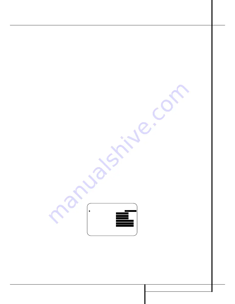
so that
X-OVER
is high-
lighted and the menu data will change to the screen
shown in Figure 4.
Figure 4
To change the setting for any of the three speaker
groups Left/Right, Center or Surrounds, press the
⁄
/
¤
Buttons
D
until the cursor is next to the
line where you wish to make a change and then
press the
‹
/
›
Buttons
E&
until the desired
setting appears. The available choices at which
point low-frequency information will be sent to
the subwoofer (or to the Front Left/Right speakers
in case subwoofer is set to OFF), rather than to
the speaker channel, are 40Hz, 60Hz, 80Hz,
100Hz, 120Hz and 200Hz. Pick the choice that is
identical to the information for the speakers, or if
an exact match is not possible, pick the closest
choice that is ABOVE the speaker’s lowfrequency
limit to avoid the creation of a low-frequency
“hole” where your system will have no bass
information.
In cases where
LARGE
has been selected as the
front channel speaker option and
LFE+L/R
has been selected as the subwoofer option, the
front channel sound information below the cross-
over point selected for the L/R front speakers
(when fronts are set to "Small") will be sent to
BOTH the front channel speakers and the sub-
woofer.
When all speakers are set to
LARGE
the
crossover point for the fronts (selectable when
they are set to "Small") will affect the LFE signal
and the bass support for the front speakers by the
sub (when the sub is set to L/R+LFE, see above)
only. In that case the default value "100Hz"
should be kept or selected for the crossover point
for the L/R fronts (selectable when they are
"Small") as it´s indicated (and marked by *)
behind the
LEFT/RIGHT
line in the speaker
setup menu when the X-OVER option is selected.
Note that the crossover point for the surround
speakers and the surround back speakers will be
identical. That´s why no crossover point for the
surround back speakers is selectable or shown in
the menu.
Important Note
: All settings for the crossover
points will be "Global", i.e. they will be identical
for all inputs no matter if the BASSMANAGER
(see above) was configured for "Global" or
"Independent".
10. When all speaker selections have been made,
press the
¤
Button
D
until the cursor is next
to the
BACK T O MASTER MENU
line and
press the
Set Button
F
to return to the Main
menu.
11. The Speaker Configuration may also be
changed at any time without using the full-OSD
on-screen menu system by pressing the
Speaker
Selector
6
on the front panel or
'
on the
remote control. Once the button is pressed,
FRONT SPEAKER
will appear in both the
lower third of the video display and the
Main
Information Display
˜
.
Within five seconds, either press the
‹
/
›
buttons
7 $
on the front panel or the
⁄
/
¤
buttons
D
on the remote to select a different speaker
position, or press the
Set
Button
@
F
to
begin the adjustment process for the front left
and right speakers.
* * S P E A K E R S E T U P * *
M O D E : S I Z E
X - O V E R
L E F T / R I G H T :
1 0 0 H Z
C E N T E R :
1 0 0 H Z
S U R R O U N D :
1 0 0 H Z
S U R R B A C K :
- - - - -
S U B W O O F E R :
- - - - -
B A S S M G R :
G L O B A L
B A C K T O M A S T E R M E N U
System Configuration


