


INSTALLATION AND CONNECTIONS
17
Installation and Connections
Black
Yellow
Red
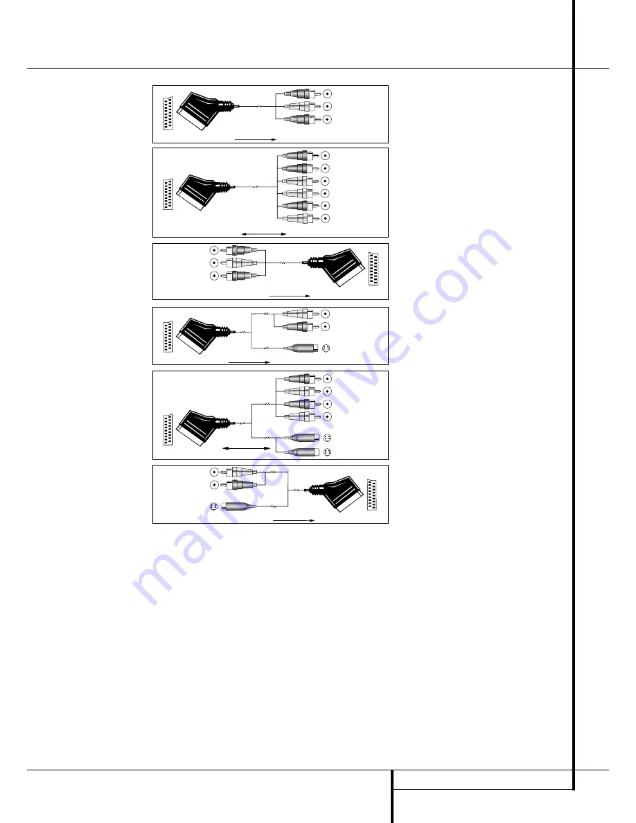
Figure 1:
SCART/Cinch-Adapter for
playback;
signal flow:
SCART
→
Cinch
Black
Red
Blue
Yellow
Green
White
Figure 2:
SCART/Cinch-Adapter for
record and playback;
signal flow:
SCART
↔
Cinch
Black
Yellow
Red
Figure 3:
Cinch/SCART-Adapter for
playback;
signal flow:
Cinch
→
SCART
Rot
Schwarz
S-Video In
Figure 4:
SCART/S-Video Adapter
for playback;
signal flow:
SCART
→
Cinch
Schwarz
Rot
Blau
Gelb
S-Video In
S-Video Out
Figure 5:
SCART/S-Video Adapter
for record and playback;
signal flow:
SCART
↔
Cinch
Rot
Schwarz
S-Video Out
Figure 6:
SCART/S-Video Adapter
for playback;
signal flow:
Cinch
→
SCART
Black
Yellow
Red
Black
Red
Blue
1
Yellow
Green
1
White
Black
Yellow
Red
Red
Black
S-Video In
Red
Black
S-Video Out
Black
Red
Blue
1
Yellow
S-Video In
S-Video Out
1
Also other colours possible, e.g. brown and grey.
Important Note for the Use of
SCART-Cinch Adapters:
When video sources are connected to the TV
directly with a SCART cable, specific control
signals apart from Audio/Video signals will be
fed to the TV. These specific signals are: With all
video sources, the signal for automatic input
selection that switches the TV automatically to
the appropriate input as soon as the video
source is started. And with DVD players, the
signals automatically turning the TV to 4:3/16:9
format (with 16:9 TVs or with 4:3 TVs with
selectable 16:9 format) and turning the RGB
video decoder of the TV on or off, depending on
the DVD player´s setting. With any adapter cable,
these control signals will be lost and the
appropriate setting of the TV must be made
manually.
Note for RGB signal with SCART:
If you use a unit providing RGB signals on a
SCART output (as e.g. most DVD players do) and
you want to use that RGB signal, this SCART
output must be connected directly to your TV.
Although the AVR 5550 RDS can switch three-
way video signals (like component signals
Y/Pb/Pr), most TVs need separate sync signals
for RGB (also with SCART) that cannot be
switched and provided by the AVR 5550.
RGB signals can be pathed through
the AVR 5550 only when no separate sync
signal is needed (see last ”Video Connection
Note” on page 16).


