background image

SYSTEM CONFIGURATION

19

Input Setup

The first step in configuring the AVR 3500 is to
select an input. This may be done by pressing
the front panel 

Input Source Selector

!

until the desired input’s name appears momen-
tarily in the 

Main Information Display

N

,

and the green LED lights next to the input’s
name in the front panel 

Input Indicators

Ô

.

The input may also be selected by pressing the
appropriate Input Selector on the remote control

46%

.

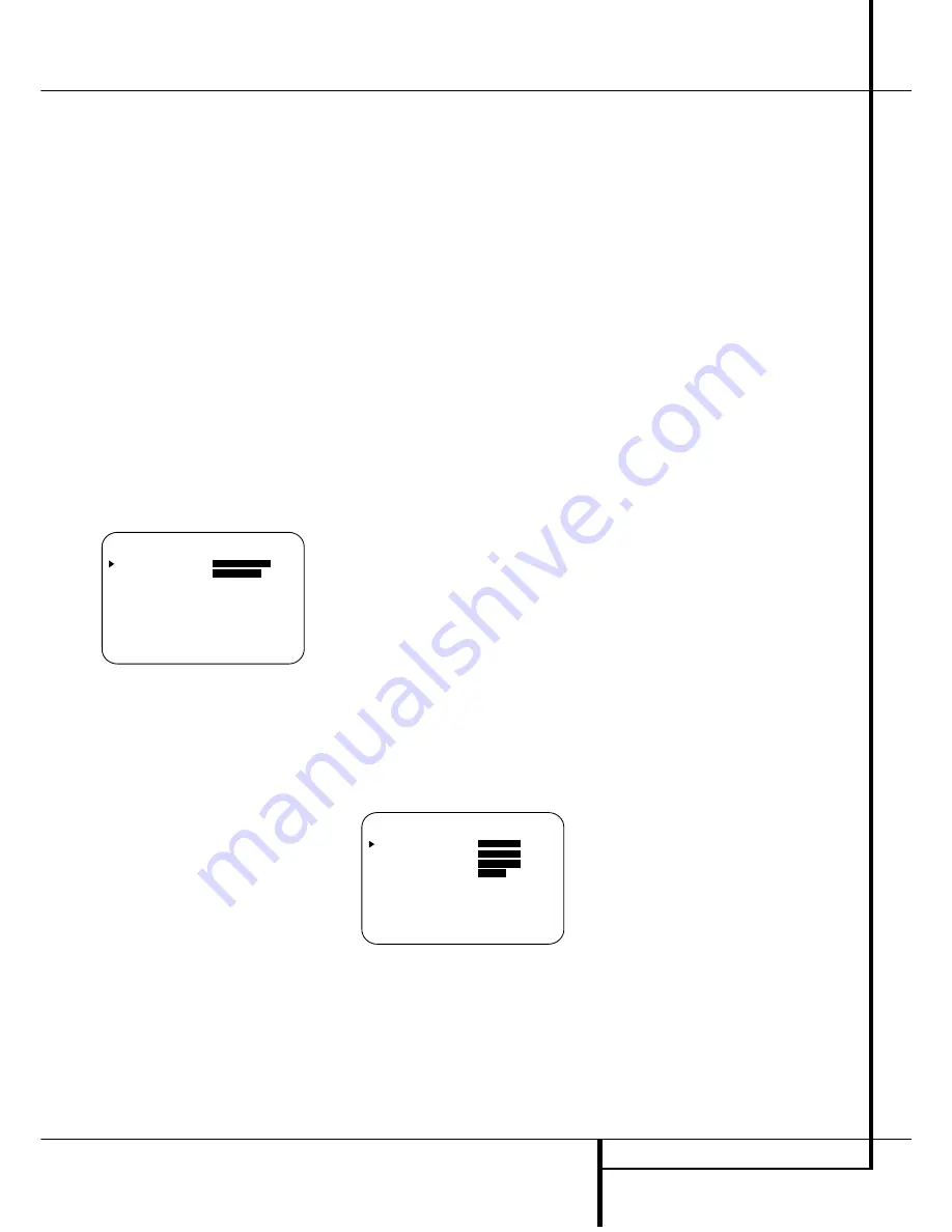
When using the full-OSD system to make the
setup adjustments, press the 

OSD

button 

L

once so that the 

MASTER MENU

(Figure

1) appears. Note that the 

cursor will be next

to the 

INPUT SETUP

line. Press the 

Set

button 

F

to enter the menu and the

INPUT S E T U P

menu (Figure 2) will

appear on the screen. Press the 

/

buttons

E

until the desired input name appears in

the highlighted video, as well as being indicated
in the front panel 

Input Indicators

Ô

by the

green LED next to the desired input name. If the
input will use the standard left/right analog
inputs, no further adjustment is needed.

Figure 2

If you wish to associate one of the digital inputs
with the selected input source, press the 

¤

but-

ton 

D

on the remote while the 

INPUT

S E T U P

menu (Figure 2) is on the screen, and

note that the on-screen cursor will drop down to
the 

DIGITAL I N

line. Press the 

/

but-

tons 

E

until the name of the desired digi-

tal input name appears. To return to the

A N A L O G

input, press the buttons until the

word 

A N A L O G

appears. When the correct

input appears, press the 

¤

button 

D

until the

cursor appears next to 

R E T U R N T O

M E N U

, and press the 

Set

button 

F

.

To change the digital input associated with the
input selected at any time using the discrete
function buttons and the semi-OSD system,
press the 

Digital Input Select

button 

Ò

G

on the front panel or the remote. Within five sec-
onds, make your input selection using the

Selector

buttons on the front panel 

5

or the

/

¤

buttons 

D

on the remote until the

desired digital or analog input is shown in the

Main Information Display

N

and in the

lower third of the video display connected to the
AVR 3500. Then press the

Set 

button 

F

to

enter the new digital input assignment.

Speaker Setup

This menu tells the AVR 3500 which type of
speakers are in use. This is important as it
adjusts the settings that determine which
speakers receive low frequency (bass) informa-
tion. For each of these settings use the

L A R G E

setting if the speakers for a

particular position are traditional full-range
loudspeakers that are capable of reproducing
sounds below 100Hz. Use the 

S M A L L

set-

ting for smaller, frequency-limited satellite
speakers that do not reproduce sounds below
100Hz. Note that when “small” front (left and
right) speakers are used, a subwoofer is
required to reproduce low frequency sounds. If
you are in doubt as to which category describes
your speakers, consult the specifications in the
speakers’ owner’s manual, or ask your dealer.
Remember that the speaker setup must be
made individually for each input in use.

It is best to select the Dolby Pro Logic II mode
for making the speaker setup. For that press the

Surround Mode Selector

7

on the front

panel until any Pro Logic II mode is indicated in
the display or press the 

Surround Mode

Selector

A

and select any Pro Logic II mode

with the 

/

¤

Selector Buttons

D

. Note

that with the currently selected input all speaker
settings will be copied to other surround modes
too (as far as possible) and need not be repeat-
ed with any other mode (but with each input
used).

1. It is easiest to enter the proper settings for
the speaker setup through the 

SPEAKER

S E T U P

menu (Figure 3). If that menu is not

alredy on your screen from the prior adjust-
ments, press the 

OSD

button 

L

to bring up

the 

MASTER MENU

(Figure 1), and then

press the 

¤

button 

D

twice so that the cursor

is on the 

S P E A K E R S E T U P

line. At this

point, press the 

Set

button 

F

to bring up the

S P E A K E R S E T U P

menu (Figure 3).

Figure 

3

2. When the 

S P E A K E R S E T U P

menu

appears, the on-screen cursor 

will be at the top

of the list of speaker positions, pointing toward
the 

LEFT

/

RIGHT

line, which sets the con-

figuration for the front left and right speakers. If
you wish to make a change to the front speakers
configuration, press the 

/

buttons 

E

so

that either 

LARGE

or 

SMALL

appears,

matching the appropriate description from the
definitions shown above.

When 

SMALL

is selected, low frequency front

channel sounds will be sent only to the subwoofer
output. Note that if you choose this option and
there is no subwoofer connected, you will not
hear any low frequency sounds from the front
channels. This setting is not available with stereo
mode to ensure purest sound by bypassing the
crossovers of the DSP´s.

When 

LARGE

is selected, a full-range output

will be sent to the front left and front right out-
puts. Depending on the choice made in the

SUBWOOFER

line in this menu (see below),

the front left and right bass information may also
be directed to a subwoofer.

Important Note:

When a speaker set with two

front satellites and a passive subwoofer is used,
connected to the 

front speaker outputs

D

,

the fronts must be set for 

LARGE

.

3. When you have completed your selection for
the front channel, press the 

¤

button 

D

on the

remote to move the cursor to 

CENTER

.

4. Press the 

/

buttons 

E

on the remote

to select the option that best describes your
Center speaker based on the speaker definitions
shown on this page.

When 

SMALL

is selected, low frequency cen-

ter channel sounds will be sent to the Fronts, if
they are set for LARGE and Sub is turned off.
When Sub is on, low frequency center channel
sounds will be sent to the subwoofer only.

When 

LARGE

is selected, a full-range output

will be sent to the center speaker output, and
with analog and digital surround modes (except
with the Pro Logic II Music mode) NO center
channel signal will be sent to the subwoofer out-
put.

When 

NONE

is selected, no signal will be sent

to the center channel output. The receiver will
operate in a “phantom” center channel mode
and center channel information will be sent to
the left and right front channel outputs and its
bass will be sent to the subwoofer output too as
long as 

S UB L/R+LFE

is selected in the

SUBWOOFER

line in this menu (see below).

This mode is needed if no Center speaker is
used. Note that for the use of Logic 7C surround
mode a Center speaker is needed, but Logic 7M
works well without a Center too.

5. When you have completed your selection for
the center channel, press the 

¤

button 

D

on

the remote to change the cursor to 

SURROUND

.

6. Press the 

/

buttons 

E

on the remote

to select the option that best describes the sur-
round speakers in your system based on the
speaker definitions shown on this page.

*   S P E A K E R   S E T U P   *

L E F T / R I G H T :  

S M A L L


C E N T E R         :  

S M A L L

S U R R O U N D     :  

S M A L L

S U B W O O F E R   :  

S U B

R E T U R N   T O   M E N U

    *   I N P U T   S E T U P   *    

I N P U T           :

V I D E O   1

D I G I T A L   I N :

A N A L O G

R E T U R N   T O   M E N U

System Configuration

Содержание AVR 3500

Страница 1: ...AVR 3500Audio VideoReceiver OWNER S MANUAL AVR 3500 RDS DTS MP3 PCM 3ST OSD DSP SL SR VMAxNF LOGIC 7CM PLII KHz MHz OPT123 COAX123 ANALOG AUTO RDS TA TUNED ST MEM Power for the Digital Revolution ...

Страница 2: ...s 35 Full OSD Time Out Adjustment 36 Programming the Remote 36 Programming the Remote with Codes 37 Macro Programming 38 Programmed Device Function 38 Volume Punch Through 39 Channel Control Punch Through 39 Transport Control Punch Through 39 Resetting the Remote Memory 40 Function List 42 Setup Code Tables 52 Troubleshooting Guide 52 Processor Reset 53 Technical Specifications Table of Contents T...

Страница 3: ...rs or playback devices with the power and fidelity you expect from Harman Kardon Another Harman Kardon exclusive is VMAx which uses proprietary processing to create an open spacious sound field even when only two front speakers are available In addition to providing a wide range of listening options the AVR 3500 is easy to configure so that it provides the best results with your speak ers and spec...

Страница 4: ...t proper space is provided both above and below the unit for ventilation If this product will be installed in a cabinet or other enclosed area make certain that there is sufficient air movement within the cabinet Under some circumstances a fan may be required Do not place the unit directly on a carpeted surface Avoid installation in extremely hot or cold locations or an area that is exposed to dir...

Страница 5: ...nes are connected 5 Selector Buttons When you are establish ing theAVR 3500 s configuration settings use these buttons to select from the choices available as shown in the Main Information Display Ú 6 Tone Mode Pressing this button enables or disables the Balance Bass and Treble tone con trols When the button is pressed so that the words TONE IN appear in the Main Information Display Ú the setting...

Страница 6: ...nce Control Turn this control to change the relative volume for the front left right channels NOTE For proper operation of the surround modes this control should be at the midpoint or 12 o clock position Treble Control Turn this control to modify the high frequency output of the left right chan nels by as much as 10dB Set this control to a suitable position for your taste or room acoustics Volume ...

Страница 7: ...e modes include Hall 1 Hall 2 Theater and 5 Channel Stereo K Logic 7 Mode Indicators These indicators illuminate when the Logic 7 mode is in use LOGIC 7C appears for the Cinema version of Logic 7 LOGIC 7M appears for the Music version of Logic 7 See page 26 for a description of the Logic 7 Modes L Tuned Indicator This indicator illuminates when a station is being received with sufficient sig nal s...

Страница 8: ...icators will show the minutes remaining before the AVR 3500 goes into the Standby mode See page 25 for more information on the Sleep function U Memory Indicator This indicator flashes when entering presets and other information into the tuner s memory V Stereo Indicator This indicator illuminates when an FM station is being tuned in stereo W RDS Indicator This indicator illuminates when the statio...

Страница 9: ...ks of an audio recorder 2 Video 1 Audio Inputs Connect these jacks to the PLAY OUT audio jacks on a VCR or other video source 3 AM Antenna Connect theAM loop antenna supplied with the receiver to these terminals If an externalAM antenna is used make connections to the AM and GND terminals in accordance with the instructions supplied with the antenna 4 Video 1 Audio Outputs Connect these jacks to t...

Страница 10: ... Power switch 1 is on Note The total power consumption of all devices connected to the accessory outlets should not exceed 100 watts from the Unswitched Outlet G and 50 W from the Switched Outlet F H AC Power Cord Connect the AC plug to an unswitched AC wall output I DVD Video Inputs Connect these jacks to the composite or S Video output jacks on a DVD player or other video source J Video 1 Video ...

Страница 11: ... Up Down Clear Button Memory Button Delay Prev Ch Button Speaker Select Spare Button Volume Up Down TV Video Selector SPL Indicator Select 6 Channel Direct Input Mute NOTE The function names shown here are each button s feature when used with the AVR Most buttons have additional functions when used with other devices See page 40 41 for a list of these functions POWER AVR AM FM VCR 6CH ON OFF SLEEP...

Страница 12: ... in the Sleep mode After the time shown in the display the AVR 3500 will automatically go into the Standby mode Each press of the button changes the time until turn off in the fol lowing order Hold the button pressed for two seconds to turn off the Sleep mode setting Note that this button is also used to change channels on your TV VCR and SAT receiver when selected A Surround Mode Selector Press t...

Страница 13: ... Prev Ch Press this button to begin the process for setting the delay times used by the AVR 3500 when processing surround sound After pressing this button the delay times are entered by pressing the Set button F and then using the buttons D to change the setting Press the Set button again to complete the process See page 21 for more information Button Press this button to change a set ting or sele...

Страница 14: ... mend that you use cables with an area less than 1mm2 due to the power loss and degradation in performance that will occur Cables that are run inside walls should have the appropriate markings to indicate listing with UL CSA or other appropriate testing agency stan dards Questions about running cables inside walls should be referred to your installer or a licensed electrical contractor who is fami...

Страница 15: ...VCR con nect the Out plugs to the Out jacks on the AVR Note that with some adapter types it may be just turned around If no signal is audible visi ble when the VCR is playing connect the Out plugs to the In jacks on the AVR and turned around If the adapter plugs are not labeled in that way pay attention to the signal flow direc Black Yellow Red Figure 1 SCART Cinch Adapter for playback signal flow...

Страница 16: ...when the unit is on completely This is recom mended for devices that have no power switch or a mechanical power switch that may be left in the ON position NOTE Many audio and video products turn to Standby mode only when they are used with switched outlets and cannot be fully turned on using the outlet alone without a remote control command The Unswitched G outlet will receive power as long as the...

Страница 17: ...lines you ll find that it takes some experimentation to find the correct location for the front speakers in your particular installation Don t be afraid to move things around until the system sounds correct Optimize your speakers so that audio transitions across the front of the room sound smooth Surround speakers should be placed on the side walls of the room at or slightly behind the listening p...

Страница 18: ... the current menu selection That selection will also be shown in the Main Information Display N Selecting the On Screen display The full OSD system is always available by press ing the OSD button L When this button is pressed the MASTER MENU Figure 1 will appear and adjustments are made from the individual menus Note that the menus will remain on the screen for 20 seconds after the latest action w...

Страница 19: ...d to other surround modes too as far as possible and need not be repeat ed with any other mode but with each input used 1 It is easiest to enter the proper settings for the speaker setup through the SPEAKER SETUP menu Figure 3 If that menu is not alredy on your screen from the prior adjust ments press the OSD button L to bring up the MASTER MENU Figure 1 and then press the button D twice so that t...

Страница 20: ...tor buttons 5 or the buttons D on the remote to select a different speaker position or press the Set Button ÓF to begin the adjustment process for the front left and right speakers When the Set button Ó F has been pressed and the system is ready for a change to the front speaker setting the on screen display and Main Information Display N will read F LARGE or F SMALL depending on the current set t...

Страница 21: ...y cause the arrival of front channel sounds to become disconnected from surround channel sounds To resynchronize the front center and surround channels follow these steps 1 Measure the distance from the listening viewing position to the front speakers in meters 2 Measure the distance from the listening viewing position to the surround speakers 3 Subtract the distance to the surround speakers from ...

Страница 22: ...e or no sound in the surround channels This is because they are only used when a movie director or sound mixer specifically places sound there to create ambiance a special effect or to continue action from the front of the room to the rear When the output levels are properly set it is normal for surround speakers to oper ate only occasionally Artificially increasing the volume to the rear speakers...

Страница 23: ...een cursor is next to the OUTPUT ADJUST line If you are not at the main menu press the OSD button L to bring up the MASTER MENU Figure 1 and then press the buttons D three times so that the on screen cursor is next to the Output adjust line Press the Set button F to bring the OUTPUT ADJUST menu Figure 7 to the screen Figure 7 As soon as the new menu appears you will hear a test noise circulate fro...

Страница 24: ... for any other mode select that mode with any input and repeat the level adjustment described above This will also allow you to com pensate level differences between speakers that may be different with each surround mode or to increase or decrease the level of certain speakers intentionally depending on the surround mode selected Note Output level adjustment is not available for the VMAx or Surrou...

Страница 25: ...t source may also be changed by pressing the front panel Input Source Selector button Each press of the button will move the input selection through the list of available inputs As the input is changed the AVR 3500 will automatically switch to the digital input if selected surround mode and speaker configura tion that were entered during the configuration process for that source The front panel Vi...

Страница 26: ...not adjustable of a standard live performance theater with stereo and even pure mono sources HALL 1 The two Hall modes create sound fields that resemble a small HALL 1 or Delay time not adjustable HALL 2 medium sized HALL 2 concert hall with stereo and even pure mono sources VMAx Near When only the two front channel loudspeakers are used Harman s patented VMAx mode No surround channels VMAx Far de...

Страница 27: ... current mode in the Surround Mode Indicators list ˆ on the front panel NOTE The name of each Surround Mode will scroll across the bottom of the on screen display and through the Main Information Display N while the modes are being selected To avoid exiting from the surround mode selection process be certain to push the buttons D while a mode name is still visible Note that the Dolby Digital or DT...

Страница 28: ...rst select its input using the remote or front panel controls as outlined in this manual in order to feed its video signal if any to the TV monitor and to provide its analog audio signal for record ing When the digital input appropriate with the DVD player is not selected automatically due to the input settings made earlier during the system configuration see page 19 select the digital source by p...

Страница 29: ...he Night mode To turn the Night mode off press the buttons D until the message in the lower third of the video display and the Main Information Display N reads D R OFF When the Night mode is active the Night Mode Indicator O will also illuminate The Night mode may also be selected to always be on at either level of compression as soon as the Dolby Digital mode is turned on using the options in the...

Страница 30: ...r the level is too low After the output levels of all channels are aligned press the SPL Indicator Select to turn the sensor and indicator off The channel output may also be adjusted using the full OSD on screen menu system First set the volume to a comfortable listening level using the Volume Control Then press the OSD button L to bring up the MASTER MENU Figure 1 Press the Button D until the on ...

Страница 31: ...ated tap the Tuning button 8 K to advance one frequen cy increment at a time or press and hold it to locate a specific station When the TUNED indi cator L illuminates the station is properly tuned and should be heard with clarity 5 Stations may also be tuned directly by press ing the Direct button J and then pressing the Numeric Keys H that correspond to the station s frequency The desired station...

Страница 32: ...n the display Depending on signal quality it may take up to 30 seconds for the text message to appear in that time the word TEXTwill flash in the Information Display when RT is selected The current time of day CT Note that it may take up to two minutes for the time to appear in that time the word TIMEwill flash in the information display when CT is selected Please note that the accuracy of the tim...

Страница 33: ...first station that has RDS data that matches the desired selec tion and acceptable signal strength for quality reception 4 The tuner will make up to one complete scan of the entire FM band for the next station that matches the desired PTY type and has accept able reception quality If no such station is found the display will read NONEfor some seconds and the tuner will return to the last FM statio...

Страница 34: ...is turned off Turn On Volume Level As is the case with most audio video receivers when the AVR 3500 is turned on it will always return to the volume setting in effect when the unit was turned off However you may prefer to always have the AVR 3500 turn on at a specific setting regardless of what was last in use when the unit was turned off To change the default condition so that the same volume lev...

Страница 35: ... menu this is a permanent setting change and the time out entry will remain in effect until it is changed even when the unit is turned off If you wish to make other adjustments in the menu press the Buttons D until the on screen cursor is next to the desired setting or the RETURN TO MENU line and press the Set button F If you have no other adjust ments to make press the OSD Button L to exit the me...

Страница 36: ...ransport function transmitted 6 Try all of the functions on the remote to make certain that the product operates properly Keep in mind that many manufacturers use a number of different combinations of codes so it is a good idea to make certain that not only does the Power control work but that the volume channel and transport controls work as they should If functions do not work properly you may n...

Страница 37: ...not lit red and AVR functions shall be pro grammed 3 When all the steps have been entered press the Sleep button 9 to enter the commands The red light under the Input Selector 45 will blink and then turn off Example To program the Macro 1 M button so that it turns on the AVR 3500 TV and a Sat Receiver follow these steps Press the Macro 1 button M and Mute buttons at the same time and then release ...

Страница 38: ...pears that only a few functions operate check to see if another code set will work with more buttons Depending on the brand and product type used the functions listed in the Function List tables may not correspond with the function the unit reacts on the command In these cases it s a good idea to edit the reaction of the unit into the corresponding line of the table or to set up a separate list Wh...

Страница 39: ...ollow these steps 1 Press the Input Selector 4 for the device you wish to have the channel control associated with and the Mute button at the same time until the red light illuminates under the Input Selector 4 and the Program SPL Indicator 2 flashes amber 2 Press the Play button x The Program SPL Indicator 2 will stop flashing and stay amber 3 Press and release the AVR 5 or Input Selector button ...

Страница 40: ... Set Set Enter 28 fl Move Adjust Right Right 29 Digital Exit Digital Input Select Open Close 30 Move Adjust Down Down 31 Delay Prev Ch Delay Adjust Return Open Close 32 1 1 1 1 33 2 2 2 2 34 3 3 3 3 35 4 4 4 4 36 5 5 5 5 37 6 6 6 6 38 7 7 7 7 39 8 8 8 8 40 Tun M Tuner Mode Chapter Repeat 41 9 9 9 9 42 0 0 0 0 43 Memory Memory Audio Time CDR Display 44 Tune Up Tune Up 45 Direct Direct Tuner Entry An...

Страница 41: ...p Up Up 25 Speaker Menu Menu Menu Menu Menu 26 fi Left Left Left Left 27 Set Enter Enter Enter Enter 28 fl Right Right Right Right 29 Digital Exit Exit Exit Exit Exit 30 Down Down Down Down 31 Delay Prev Ch Prev Channel Prev Channel Prev Channel 32 1 1 1 1 1 33 2 2 2 2 2 34 3 3 3 3 3 35 4 4 4 4 4 36 5 5 5 5 5 37 6 6 6 6 6 38 7 7 7 7 7 39 8 8 8 8 8 40 Tun M 41 9 9 9 9 9 42 0 0 0 0 0 43 Memory 44 Tune...

Страница 42: ...GA 023 088 BRUNS 023 088 BUSH 010 020 040 043 092 BUSH UK 044 CENTURY 023 088 CGE 105 CIHAN 032 COMTEL 032 CONTEC 010 CONTINENTAL EDISON 017 019 024 056 059 CROSLEY 023 088 DAEWOO 022 DANSAI 022 DECCA 032 091 DECCA UK 038 DEGRAAF 015 DIXI 022 DORIC 029 DUMONT 023 088 096 DUMONT FINLUX 012 044 DYNATRON 020 022 ELBE 095 105 ELCIT 023 032 EMERSON 023 088 ERRES 022 033 FENNER 022 FERGUSON 001 024 047 ...

Страница 43: ...99 LUMA 022 LUXOR 058 MAGNADYNE 023 088 MANESTH 022 MARANTZ 022 MARELLI 088 MARK 022 MATSUI 001 020 038 040 043 091 METZ 011 023 075 076 077 088 MINERVA 011 075 076 077 096 MITSUBISHI 007 010 011 013 020 022 023 029 034 038 039 043 046 050 057 075 076 077 079 082 083 089 090 091 092 124 NATIONAL 018 NEC 010 043 NECKERMANN 023 078 088 102 NOKIA 040 046 092 100 NORDMENDE 009 017 019 024 053 056 059 ...

Страница 44: ...5 SHARP 010 043 SIEMENS 010 011 015 075 076 077 SINGER 023 088 105 SONY 006 010 016 038 043 062 064 065 091 102 103 106 SOUND WAVE 020 STERN 022 025 TANDBERG 023 056 080 TELEFUNKEN 024 056 059 069 TENSAI 022 THOMSON 003 005 009 017 019 024 040 044 053 056 059 069 072 074 080 082 093 094 THORN 047 099 THORN FERGUSON 024 047 099 102 103 TOSHIBA 001 010 037 042 043 044 063 092 096 105 TRISTAR 099 TRI...

Страница 45: ... 015 018 039 049 054 148 DUAL 044 090 148 155 DUMONT 015 039 054 148 155 DYNATECH 039 148 ELBE 036 148 ELTA 148 EMERSON 011 032 039 062 073 127 148 155 FERGUSON 001 044 083 085 090 094 100 104 108 122 131 135 138 FINLADIA 015 054 FINLUX 015 018 019 039 044 049 053 054 103 107 143 146 147 148 149 FISHER 015 019 032 FUJITSU 148 FUNAI 039 148 GARANADA UK 107 GBC UK 054 GOLDSTAR 036 055 148 155 GOODMA...

Страница 46: ...73 127 148 155 OSAKI 039 055 148 155 OTTO VERSAND 054 098 147 155 156 157 158 PALLADIUM 148 PANASONIC 088 089 107 129 137 147 148 PATHE MARCONI 044 090 PHILIPS 006 041 043 049 050 054 082 091 109 145 146 155 PIONEER 047 054 113 145 PROLINE 039 148 QUELLE 011 044 048 054 055 098 107 109 127 RADIOLA 049 091 109 RCA 062 REALISTIC 015 019 039 049 050 147 148 REX 044 090 ROADSTAR 055 148 SABA 009 044 0...

Страница 47: ...NIC 155 UHER 044 096 ULTRAVOX 155 UNIVERSUM 147 148 149 155 156 157 158 WATSON 155 WELTBLICK 155 YAMAHA 036 044 YOKO 098 148 155 ZANUSSI 044 090 ZENDER 090 Setup Code Table CATV Maker Brand Name Code Number 3 digit List BT CABLE 007 CABLETIME 008 011 012 016 CLYDE CABLE VISION 017 DECSAT CANAL 010 FILMNET 018 019 020 FRANCE TELECOM 013 021 GEC 017 JERROLD 001 022 PHILIPS 023 PIONEER 002 SAMSUNG 00...

Страница 48: ...IA 367 KATHREIN 301 333 380 390 KOSMOS 380 LOEWE 475 LEMON 474 LORENZEN 461 462 463 464 465 MARANTZ 333 MASPRO 353 406 METZ 390 MINERVA 390 MITSUBISHI 390 MULTISTAR 380 NEC 330 336 346 373 NOKIA 367 NORSAT 346 OTTO VERSAND 390 PACE 348 353 363 364 367 424 PACE MSS SERIES 367 PANASONIC 331 424 PHILIPS 319 332 333 353 421 424 QUADRAL 466 467 468 469 470 471 472 473 QUELLE 390 RADIOLA 353 RADIX 347 R...

Страница 49: ...1 118 156 170 ARCAM 217 221 AKAI 050 177 184 AUDIOMECA 221 BSR 044 CALIFORNIA AUDIO 015 109 CAPETRONIC 070 CROWN 042 DENON 187 188 213 FISHER 055 068 FUNAI 126 GOLDSTAR 016 087 GRUNDIG 217 221 225 226 227 228 HAITAI 099 214 HARMAN KARDON 001 025 054 190 218 219 HITACHI 093 JVC 176 195 196 KENWOOD 030 062 078 079 148 151 176 178 181 KYOCERA 012 LINN 217 221 LUXMAN 077 102 MAGNAVOX 039 113 MARANTZ 0...

Страница 50: ... 081 157 172 SANYO 033 068 082 095 168 SHARP 058 105 114 151 159 167 180 181 SHERWOOD 003 041 058 105 133 230 231 232 233 234 235 236 237 238 239 240 241 242 243 SIGNATURE 040 SONY 212 103 115 116 118 132 139 163 205 206 207 208 217 T A 218 222 TEAC 011 058 085 086 106 107 110 121 137 146 154 TECHNICS 244 245 246 247 248 249 250 THETA DIGITAL 039 THOMSON 217 252 THORENS 217 221 TOSHIBA 013 074 097...

Страница 51: ... 004 GOLDSTAR 005 HARMAN KARDON 001 JVC 006 LG 005 055 064 MAGNAVOX 056 MARANTZ 059 MITSUBISHI 023 NAD 062 ONKYO 009 048 PANASONIC 024 030 044 PHILIPS 056 PIONEER 041 065 PROCEED 060 PROSCAN 003 004 RCA 003 004 SAMSUNG 053 054 SHARP 028 SONY 043 045 THOMPSON 003 004 TOSHIBA 009 058 YAMAHA 030 063 ZENITH 005 055 064 ...

Страница 52: ... certain AC power cord is plugged Main Power Switch 1 is pushed into a live outlet Check to see if outlet is switch controlled Display lights but no sound Intermittent input connections Make certain that all input and speaker or picture connections are secure Mute is on Press Mute button Volume control is down Turn up volume control Sound is heard but Front Panel Display brightness is turned off F...

Страница 53: ...le Sensitivity Loop 500µV Distortion 1kHz 50 Mod 0 8 Selectivity 9kHz 30dB Video Section Video Format PAL NTSC Input Level Impedance 1Vp p 75 ohms Output Level Impedance 1Vp p 75 ohms Video Frequency Response 10Hz 8MHz 3dB General Power Requirement AC 220 240V 50Hz Power Consumption 72W idle 580W maximum 2 channels driven Dimensions Max Width 440mm Height 166mm Depth 435mm Weight 14 1 kg Depth mea...

Страница 54: ...250 Crossways Park Drive Woodbury New York 11797 www harmankardon com Harman Consumer International 2 route de Tours 72500 Château du Loir France 2001 Harman Kardon Incorporated Part No AVR3500 OM ...

Отзывы: