HI 6600 Series Modular Sensor System User Guide
Page | 70
Configuring Profibus from the Front Panel
1)
Press the Configuration key
2)
Down arrow to Communications; press enter.
3)
Select Profibus-DP; press enter.
4)
Down arrow to select Serial Option;
5)
Press enter to toggle between Profibus-DP and Modbus. Select Profibus-DP and press enter.
6)
Down arrow to Node.
7)
Press enter to make changes to the Node. Use the arrow keys to enter node number and press enter to accept
8)
Press exit key until display returns to the Summary Display.
Initialization Procedures on the PLC
NOTE
The examples below come from the Siemens Step 7®, Simatic Manager Software. Your software will
vary from these procedures. Step 7™ is a trademark of the Siemens Corporation.
1)
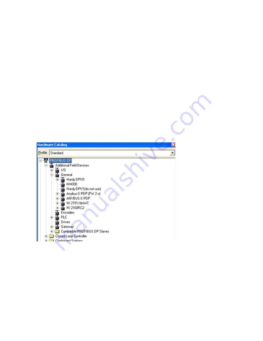
In the Siemens Step 7™, Simatic Manager, open the Hardware Catalog.
2)
Click on the “+” to expand the Additional Field Devices Folder.
3)
Click + to expand the General Folder.
4)
Double Click on “HI6000” or drag and drop the “HI6000” folder to the Profibus-DP Network. This
opens the HI 6000 PDP Parameters dialog box where you can set the address of the instrument, if
necessary.
Содержание HI 6110
Страница 16: ...HI 6600 Series Modular Sensor System User Guide Page 16 ...
Страница 44: ...HI 6600 Series Modular Sensor System User Guide Page 44 ...
Страница 96: ...HI 6600 Series Modular Sensor System User Guide Page 96 General Troubleshooting Flow Chart Index ...
Страница 97: ...HI 6600 Series Modular Sensor System User Guide Page 97 A ElectricalandMechanicalReview ...
Страница 98: ...HI 6600 Series Modular Sensor System User Guide Page 98 A1 CheckingforUnstableComponentsinaWeighingSystem ...
Страница 100: ...HI 6600 Series Modular Sensor System User Guide Page 100 B1 GuidelinestoVerifyElectricalInstallation ...
Страница 101: ...HI 6600 Series Modular Sensor System User Guide Page 101 B2 GuidelinestoVerifyMechanicalInstallation ...
Страница 102: ...HI 6600 Series Modular Sensor System User Guide Page 102 B3 VerifyConfiguration FilterSettingstoImproveStability ...
Страница 103: ...HI 6600 Series Modular Sensor System User Guide Page 103 C IntegratedTechnicianandStabilityTestOverview ...
Страница 104: ...HI 6600 Series Modular Sensor System User Guide Page 104 ENon ReturntoZero SystemwithITSummingCard ...
Страница 106: ...HI 6600 Series Modular Sensor System User Guide Page 106 G Calibration Errors During Calibration ...
Страница 107: ...HI 6600 Series Modular Sensor System User Guide Page 107 H Mechanical Installation ...
Страница 108: ...HI 6600 Series Modular Sensor System User Guide Page 108 J Electrical Inspection ...
Страница 109: ...HI 6600 Series Modular Sensor System User Guide Page 109 K InstallationCheckPoints ...
Страница 110: ...HI 6600 Series Modular Sensor System User Guide Page 110 M WeightProcessor sOptionalFrontDisplayBlankorLocked ...
Страница 128: ...HI 6600 Series Modular Sensor System User Guide Page 128 ...
Страница 130: ...HI 6600 Series Modular Sensor System User Guide Page 130 Image of HI 6600 Hardy Gateway Module II Diagram ...
Страница 131: ...HI 6600 Series Modular Sensor System User Guide Page 131 Image of HI 6610 Weight Processing Module II Diagram ...
Страница 132: ...HI 6600 Series Modular Sensor System User Guide Page 132 OptionalHI6110DisplayPanelMountingTemplate ...


