6 - Maintenance
156
2.
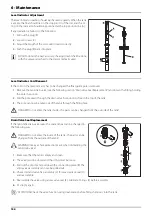
The black plastic parts are snapped together. To disassemble,
insert a flat screwdriver (B) and press, until the locking piece (A)
snaps out.
3.
With the locking piece (B) removed, place the screwdriver as
shown and pull to remove the upper part (C) of the nozzle holder.
Here the locking piece (B) and the upper part are separated (C).
4.
Inside the lower part (D), the O-ring (E) is located.
5.
Check condition and position of the O-ring. Replace if damaged or
cracked.
÷
NOTE! When seated, the O-ring is supposed to be a little out of
shape when it fits tightly around the hole in the nozzle pipe.
6.
If reused, clean the O-ring.
Содержание NAVIGATOR VPZ
Страница 4: ...1 EU Declaration 4...
Страница 72: ...3 Description 72...
Страница 135: ...6 Maintenance 135 Lubrication Plan Boom Wings 10...
Страница 174: ...6 Maintenance 174...
Страница 182: ...7 Fault Finding 182...
Страница 195: ...8 Technical Specifications 195 Hydraulic Diagrams Hydraulics for Boom of 21 24 Meters...
Страница 196: ...8 Technical Specifications 196 Hydraulics for Boom of 27 28 Meters...
Страница 198: ...8 Technical Specifications 198...
Страница 204: ...HARDI INTERNATIONAL A S Herthadalvej 10 DK 4840 N rre Alslev DENMARK...


