background image

6 - Maintenance

141

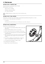
10 Hours Service - EasyCleanFilter

This filter has a clogging indicator, but even if this indicator does not 
show clogging, the filter mostly needs cleaning every 10 hours.

÷

NOTE! The controller will show a service interval message, when 
it is time for cleaning the filter.

Servicing the Filter

1.

Turn the filter lid counter-clockwise to open it.

2.

Remove lid and filter from the filter housing.

3.

Separate filter element from lid/filter guide by turning locks (A) 
outwards.

4.

Clean filter and if necessary clean the housing for larger impurities.

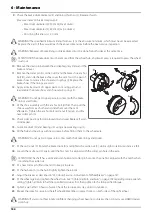
To Reassemble

1.

Grease the O-ring on the filter lid.

2.

Press the filter onto the filter guide/lid. Make sure that it has caught 
the guide. Locks (A) are turned inwards.

3.

Reassemble filter/filter lid into the housing. Make sure that it has 
caught the guide in the bottom of the housing.

4.

Turn the filter lid clockwise to close it.

±

WARNING! Always wear protective clothing and gloves before 
servicing the filter!

μ

ATTENTION! If you have difficulties with opening the filter, there is another way to handle it. 

See “Emergency Operation - EasyClean Filter” on page 181.

Содержание NAVIGATOR VPZ

Страница 1: ...www hardi international com NAVIGATOR VPZ Original Instruction book 67058800 100 version 1 00 GB 08 2020...

Страница 2: ...ctive 2006 42 EC article 2 Connecting the sprayer to the tractor makes the operator responsible for safety and health when using that combination of machines Before first use of the sprayer the owner...

Страница 3: ...rding the Machinery Directive CE marking 2009 127 EC and later amendments regarding machinery for pesticide application 2014 30 EU regarding electromagnetic compatibility EMC Electronic components on...

Страница 4: ...1 EU Declaration 4...

Страница 5: ...fety Measures Under Normal Operation 23 Protection Equipment 23 Residual Energy 24 Possible Dangers 24 Service and Maintenance Work 25 Statutory Inspection 25 Preventive Measures 25 Design Changes 26...

Страница 6: ...lic System 62 Hydraulic Blocks 62 Spray Boom 64 Boom and Terminology 64 Other Equipment 65 Control Units in the Tractor 65 IntelliTrack 65 ManualTrack 65 Drawbars 66 AutoSlant Optional 66 Nozzle Press...

Страница 7: ...ck Width 90 Turning the Wheel Rim 91 Brakes 92 Emergency and Parking Brake 92 Hydraulically Activated Brakes 92 Pneumatic Connections 93 Dual Line Air Activated Brakes 93 Single Line Air Activated Bra...

Страница 8: ...al Version optional 127 PressureEmpty i version optional 128 BoomFlush Manual Cleaning 128 Full Internal Cleaning Soak Wash 128 Outside Cleaning Use of External Cleaning Device Manual Version optional...

Страница 9: ...3 Way Valve Adjustment 159 Safety Valve Activation 159 Readjustment of Boom General Info 160 Boom Adjustment Order 161 Trapeze Locking Device 161 Horizontal Alignment of the Centre Section and Inner...

Страница 10: ...Pump Capacity 186 Other Specifications 187 Tractor Requirements 187 Hydraulic Motor for Liquid Pump 188 Filters 189 Brakes 189 Transmission Shaft 189 Temperature and Pressure Ranges 190 Technical Resi...

Страница 11: ...reading it please contact the manufacturer or your HARDI dealer A worker is hereinafter called an operator An operator is a person who installs operates configures adjusts maintains cleans repairs tra...

Страница 12: ...ment has been installed correctly and is operating properly 2 In order to ensure that health and safety conditions are maintained and that deterioration liable to result in dangerous situations can be...

Страница 13: ...them inasmuch as they affect work equipment situated in their immediate work area or site even if they do not use such equipment directly 3 The information and the written instructions shall be compr...

Страница 14: ...ial by authorized persons The results of inspection testing shall be recorded and kept Health Issues Ergonomics and occupational health aspects shall be taken fully into account by the owner Obligatio...

Страница 15: ...ollowing causes Improper use of the sprayer Improper installation commissioning operation and maintenance of the sprayer Operation of the sprayer with defective safety equipment or improperly attached...

Страница 16: ...rovided by the manufacturer of the plant protection product to be used such as This Instruction Book Must always be kept together with the sprayer Must always be easily accessible for the operator Che...

Страница 17: ...r serious physical injury if the instruction is not followed This symbol means WARNING Be alert as your safety can be involved The WARNING symbol indicates a medium risk for immediate death or serious...

Страница 18: ...mations about chemical preparation before handling the machine Observe instructions and safety rules when operating Service Carefully read the Instruction Book before handling the machine Observe inst...

Страница 19: ...isk of falling off Do not ride on platform or ladder Risk of sprayer tipping over Be aware when disconnecting the sprayer Grapping area Manual handling of the boom etc Not for drinking This water must...

Страница 20: ...er is started up all the safety and protection equipment must be properly attached and fully functional Check all safety and protection equipment regularly Repair or replace the equipment as needed Fa...

Страница 21: ...n The applicable workplace safety Follow these regulations especially when Driving on public roads and routes Comply with the appropriate statutory road traffic regulations These vary from country to...

Страница 22: ...technical training shall be considered as a specialist Due to their specialist training and their knowledge of the appropriate regulations they can evaluate the work with which they have been appointe...

Страница 23: ...nder Normal Operation Protection Equipment Only operate the sprayer if all the safety and protection equipment is fully functional Check the sprayer at least once a day for visible damage and check th...

Страница 24: ...pening due to residual energy Below are some examples on where the sprayer s residual energies may be present Mechanical Energy Springs under tension Weights exposed to gravity Heat from brake drums H...

Страница 25: ...tor s hydraulic levers in neutral position to relieve oil pressure Turn off the tractor and remove the ignition key Disconnect the hydraulic hoses connected from the tractor to the sprayer Electric sy...

Страница 26: ...the state specified by the approval It is strictly forbidden to Drill holes in the steel frame or in the running gear Increasethe size of existing holes in the steel frameor inthe runninggear Weld sup...

Страница 27: ...and Disposal Environmental Protection Carefully handle and dispose of any materials used in particular When carrying out work on oiled or lubricated sprayer parts When cleaning using solvents Always f...

Страница 28: ...feres with the operator or if the operator is trying to operate the sprayer from other places than the tractor s driver seat this can result in negligent or incorrect handling of the vehicle Risk of t...

Страница 29: ...r to people to the environment and to the sprayer Danger to people through non secured working areas Danger to people through mechanical and chemical influences Failure of important sprayer functions...

Страница 30: ...can see clearly Drive in such a waythat you always have fullcontrol over the tractor with the attachedsprayer In doing so take your personal abilitiesinto account as wellas the road traffic visibilit...

Страница 31: ...next to the vehicles and helpers may only move between the vehicles when both are at a standstill If using the tractor s three pointlinkage including lift arms lower links securethe operatinglever of...

Страница 32: ...a partially filled tank It is forbidden to Stand in or near the working area of the sprayer Climb the sprayer Stand or sit on the sprayer Stand in the turning and swivel range of the sprayer There are...

Страница 33: ...ore driving downhill switch to a low gear When making turns lower your speed Checking the Vehicle Before transporting the sprayer on a road complete the following check points for the tractor and spra...

Страница 34: ...into a well balanced and stable position Any sprayers and front rear weights connected to the tractor influence the driving behaviour and the steering and braking power of the tractor The front tracto...

Страница 35: ...osition Turn off depressurize the hydraulic system Turn off the tractor engine Engage the parking brake Remove the ignition key Havethehydraulichose linescheckedatleastonceduringacalender year by anex...

Страница 36: ...eneral Safety Instructions 36 Malfunction of Track Function DANGER Inadvertently activation of the track function IntelliTrack or SafeTrack involves a risk of accidents in the working area of the spra...

Страница 37: ...lectric components Only use the prescribed fuses If the fuses used are too highly rated the electrical system will be destroyed Risk of fire Thesprayermaybe equippedwith electroniccomponents whosefunc...

Страница 38: ...turer When turning around corners observe the permitted bending and displacement of the PTO shaft Before switching on the universal joint shaft check that the selected universaljoint shaft speed rpm o...

Страница 39: ...as well as the area used for boom folding Please note the area immediately behind the sprayer which is also defined as working area The size of the working area depends on the boom type and boom width...

Страница 40: ...nation Only fill the sprayer using a free flow of water from the mains water supply or from an external water tank Environmental Precautions It is essential to reduce the environmental impact of plant...

Страница 41: ...the sprayer to prevent unintentional movements of the sprayer Switch off the PTO Switch off the tractor and remove the ignition key to prevent unintentional starting Activate the parking brake to pre...

Страница 42: ...ing and re tighten them as necessary If electrical welding is used on the tractor and on the attached sprayer disconnect the cable to the tractor s generator and battery before carrying out electrical...

Страница 43: ...afetyLocker 5 Work lights 6A Manual Pressure SmartValve 6B Pressure SmartValve i version 7 Pressure Draining Coupler 8A Manual Suction SmartValve 8B Suction SmartValve i version 9 EasyCleanFilter 10 E...

Страница 44: ...perating Unit for Spraying 15 RinseTank 16 Lid for Tank Riser Pipe 17 CleanWaterTank Electronics Cover 18 CycloneFilter 19 Storage Position for Support Leg 20 ChemLocker 21 Hose Reel for External Clea...

Страница 45: ...atform H Rails for support I Liquid pump J DynamicFluid4 pressure regulation valve K1 Agitation valve for i version K2 Manual agitation valve L Optional hydraulic motor for liquid pump M Step Accessin...

Страница 46: ...he standard types of ID plates belonging to sprayers sold to the equivalent markets are shown below xxxxxxxxxxxxxx xxxxx xxxxx xxxxx xxxxxxxxx xxxxx xxxxxxxxx xxxx xxxx xxxxx Herthadalvej 10 4840 N rr...

Страница 47: ...ases GCWR PTRA Reserved for future use Sum of gross vehicle masses of towing vehicle and trailer USA Gross Combination Weight Rating GCWR France Poids Total Roulant Autoris PTRA 8 Not used In special...

Страница 48: ...o UV radiation and chemicals The MainTank has a purposeful design with no sharp corners for easy cleaning The filling hole is placed so it can be accessed from the platform This ensures an easy access...

Страница 49: ...the pump Pump model 464 is shown in the picture TurboFiller The TurboFiller is where you add the chemicals to be mixed with water in the main tank Capacity approximately 35 litres By operating the th...

Страница 50: ...zzles are opened Even when closing all but one nozzle on a very wide boom it is quick to achieve the correct and stable application rate The benefit is more precise application rates immediately when...

Страница 51: ...d to The active function is indicated by the indicator The handle is turned so the desired symbol is just below the black mark If the handle is turned to a position without label with a symbol unused...

Страница 52: ...s is recommended when using chemicals with a high density which will tend to settle at the bottom of the tank Agitation Valve for i version White symbols With the electrically adjustable agitation val...

Страница 53: ...pressure can be fitted at each boom section Nozzle filters are fitted at each nozzle A coarse filter is located below the top cover for the MainTank ATTENTION All the filters should be in use and thei...

Страница 54: ...es the spray pressure gauge a clogging indicator is installed This works as a vacuum gauge for the filter during operation the pointer moves from green towards red if the filter starts clogging Cloggi...

Страница 55: ...eturn flow to prevent filter from clogging during spraying This position is used when rinsing the boom if the MainTank is empty C This position is marked with 3 dots Flushing position which is used if...

Страница 56: ...singTank level indicator is placed at the platform Capacity approximately 500 litres CleanWaterTank A CleanWaterTank is integrated into theright side cover It is accessed for filling at the sprayer s...

Страница 57: ...Ejector for TurboFiller 26 Tank Hose for TurboFiller 27 FastFiller Coupler 31 Pressure Draining Coupler 43 Flowmeter 45 Boost Valve 47 Drain Valve 48 External FastFiller Valve 49 Bypass Valve for Spr...

Страница 58: ...raining Coupler 33 Spray Gun for External Cleaning 34 Restrictor 35 BoomPrime Pressure Control Valve 37 BoomPrime Pressure Gauge 42 BoomPrime One Way Valve 43 Flowmeter 44 BoomPrime Valve 45 Boost Val...

Страница 59: ...ng 34 Restrictor 35 BoomPrime Pressure Control Valve 37 BoomPrime Pressure Gauge 38 Dilution Valve Boost Line 39 Dilution Valve Agitation 40 Dilution Valve Suction 41 Dilution Valve Rinsing 42 BoomPri...

Страница 60: ...n B Liquid for BoomPrime is led through a valve D just before the flowmeter F This valve operates in opposite phase When priming the direction of the liquid flow will be reversed The liquid will be fe...

Страница 61: ...or NOTE Please refer to the SmartCom UT instruction book for instructions on operation of the DilutionKit from the controller in the tractor TankDilution Water from the RinseTank is sent into the Main...

Страница 62: ...er are described below Spray Boom The main hydraulic block which distributes hydraulic fluid for the boom controls On some booms the hydraulic block is positioned horizontally ParaLift This hydraulic...

Страница 63: ...losed centre hydraulics see the tractor s instruction book or ask your tractor dealer IntelliTrack Hydraulics This hydraulic block distributes hydraulic fluid for the IntelliTrack steering functions A...

Страница 64: ...The boom is trapeze suspended and hydraulically operated Booms are available in 21 24 27 and 28 meters working width The booms is provided with spring loaded breakaway on each side The terminology is...

Страница 65: ...e driving speed is too high for the given turning radius If aTankGauge is fitted the tank filling level is also taken into account Advantages with IntelliTrack A small turning radius A better precisio...

Страница 66: ...te pressure gauge is integrated at the top of the platform This pressure gauge measures the working pressure in the boom pipes as close to the nozzles as possible The outputs stated in the nozzle char...

Страница 67: ...lifting the cover up Main Components A SmartCom box B Electric junction box for road lights C Power Distribution Unit for SmartCom D CleanWaterTank integrated in the side cover The CleanWaterTank is...

Страница 68: ...al tank volume 5 for volumes above 20 of the nominal tank volume RinseTank The actual water level in the RinseTank can be observed in the tube C A yellow ball floating inside the tube indicates the wa...

Страница 69: ...used for storing food beverages or other items meant for consumption External Cleaning Device This equipment comprises a hose reel and a spray gun for cleaning the complete sprayer externally in the f...

Страница 70: ...work light B is turned on of by activating a switch D inside the left side cover C Open the cover to turn on the light ATTENTION It is recommended to switch OFF the rear working lights of the tractor...

Страница 71: ...ck bracket B will then automatically be lowered onto the extended piston rod by means of another hydraulic cylinder C when the boom is fully folded The lock bracket will now prevent the piston rod fro...

Страница 72: ...3 Description 72...

Страница 73: ...n the tow hitches at the rear end A or a hook can be fastened into the hole in the front end of the sprayer B as shown Before Putting the Sprayer Into Operation Although the sprayer has been supplied...

Страница 74: ...ith the linchpin Jack Up the Sprayer When the sprayer needs wheel mounting or changing of wheels wheel bearings or brakes jack up the sprayer under the axle as shown Notice the axle load kg in Tyre Pr...

Страница 75: ...ore on tractor requirements see Tractor Requirements on page 187 Applicable Tractors Fill out this form showing the combinations of tractor and sprayer Sprayer Model Year Identification number The spr...

Страница 76: ...ter Also NEVER cross over a rotating PTO shaft to reach the other side of the sprayer 7 Prevent protection guards from rotating by attaching the chains allowing sufficient slack for turns 8 Make sure...

Страница 77: ...rods instead of cylinders All drawbars are fastened to the underside of the sprayer near the rear axle with 6 bolts secured by lock nuts Furthermore the drawbar is supported by 2 bolts secured with lo...

Страница 78: ...n the drawbar Turn the turnbuckles A until the measure is correct 3 Retighten the counternuts B again Transport Lock for Drawbar The transport lock is a safeguard that will keep the drawbar in a centr...

Страница 79: ...and horizontal the tractor hitch point must not have any sidewards movement Procedure when connecting the sprayer to the tractor 1 Connect the sprayer 2 Drive forward with the sprayer following the t...

Страница 80: ...air trapped in the system which can cause violent movements of the boom DANGER Hydraulic leaks Never use your fingers to locate a leakage in any part of the hydraulic system Due to high pressure hydr...

Страница 81: ...tivating a hydraulic lever in the tractor If the reaction time for the hydraulic function is relatively short continue your work with this restrictor installed If the reaction time seems too long befo...

Страница 82: ...sprayer if the operator finds it necessary ATTENTION The throttle valve only needs slight adjustments to change the speed significantly ATTENTION If the boom moves too fast Risk of premature wear and...

Страница 83: ...t If rear lights are installed connect the plug for rear lights to the tractor s 7 pin socket and check the function of rear lights stop lights side lights and direction indicators on both sides befor...

Страница 84: ...he front corner cover Check the tractor s instruction book for information regarding attachment points Supplied are three tubes B for fitting One two or all three may be used They can be bent and shor...

Страница 85: ...ion Distance from centre of the sensor to top of the brake drum 412 mm brake drum 60 mm 400 mm brake drum 75 mm 3 Adjustment of the air gap begins with the sensor directly opposite one of the bolts E...

Страница 86: ...mPrime pressure by 1 bar on the adjustment screw A ATTENTION If not adjusted correctly the nozzles will not close i e they will drip when the spraying is stopped or the tubes will not be primed The po...

Страница 87: ...the suction SmartValve is turned to the unused position and the pressure SmartValve is set to MainTank Otherwise spraying liquid may hit you when opening the filter and thereby draining the MainTank...

Страница 88: ...nless the boom and centre section are fully supported on both sides in a safe way 2 Loosen the locking bolt A 3 Remove the cross pin B from position 1 4 Place the cross pin B in position 2 5 Fasten th...

Страница 89: ...ent requirements can be given as this may vary with local driving conditions 1 Loosen the bolt B 2 Remove the Allen screw A 3 Remove one or more spacer plates from the storage position 4 Push the rubb...

Страница 90: ...ower the wheel to the ground 9 Repeat the procedure on the right wheel 10 Check if the distance from centre tyre to centre of rear frame is equal at the right and left side 11 Retighten bolts and whee...

Страница 91: ...the table below Rim Size Wheel Bolts Track Width Increases by 270 95 R38 8 pcs 322 mm 270 95 R48 8 pcs 322 mm 300 95 R46 8 pcs 222 mm 300 95 R52 8 pcs 222 mm 340 85 R48 8 pcs 222 mm 380 85 R34 8 pcs 3...

Страница 92: ...he rope breaks ATTENTION To ensure safe engagement and to avoid damages to the parking brake use a rope with an ultimate stress between 690 and 785 N WARNING Release the parking brake before driving H...

Страница 93: ...function as described Disconnect Air Hoses When disconnecting the air hoses from the tractor the brake relieve valve A is pushed out and the brakes will be fully engaged Moving Sprayer It is possible...

Страница 94: ...he snap coupler protection flap away 2 Connect the snap coupler to the tractor outlet with black colour code 3 Let the air compressor fill the sprayers air reservoir 4 Check brake circuit for leaks Lo...

Страница 95: ...bed in this instruction book a new risk assessment and a workplace assessment must be completed for this use This obligation lies with the owner and operator according to EU directive 2009 104 EC see...

Страница 96: ...Tank Black Blue 97821900 Suction from the RinseTank Black Blue 97822000 Filling of the MainTank from an external tank Black Blue 97822100 Filling of the MainTank Black Green 97810300 Spraying Pressuri...

Страница 97: ...power lines Keep from using the folding unfolding functions in areas with overhead power lines Unintended boom movements may cause contact with overhead power lines causing a risk of fatal accidents...

Страница 98: ...y pressing for approximately 5 seconds The symbol is now shown on the controller display Folding Indicator From the tractor cabin look for the yellow indicator J to be visible in the slot hole in the...

Страница 99: ...unintended folding unfolding The boom must rest on the rubber pads O during transport DANGER The transport locks must both be locked correctly before road transport If not there is a risk of unintent...

Страница 100: ...turn Never slow down too fast never brake heavily and never stop suddenly in a curve or when turning on a hillside when the sprayer is articulated Be careful when turning on uneven ground Set the trac...

Страница 101: ...lustrated NOTE Dashed lines and valve symbols indicates optional equipment and functions 1 Spraying with suction from the MainTank and using agitation in the MainTank 2 Filling chemicals using the Tur...

Страница 102: ...st be ON and blinking Automatic spray pressure regulation The regulation valve controls the main spray pressure This is default selection when the controller is powered ON and it should remain here du...

Страница 103: ...25 metres from non public water supplies for drinking purposes and from treatment sumps and cesspools of drainage systems 3 50 metres from surface water watercourses lakes and coastal waters and from...

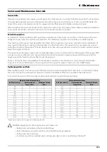
Страница 104: ...lve to External Filling Device 4 Press to close the agitation valve NOTE If AutoFill is available the amount of water to be filled can be setup before proceeding with step 5 5 Activate external fillin...

Страница 105: ...lling process Now disengage the pump 9 Disconnect the suction hose and replace the cap DANGER Prevent contamination or injury Do not open the suction valve for the External Filling Device unless the p...

Страница 106: ...TION For cleaning and inspection purpose the RinseTank is accessible via the tank lid on top of the tank Filling the CleanWaterTank To fill the CleanWaterTank 1 Remove the tank lid 2 Fill with clean w...

Страница 107: ...lean the sprayer immediately after use WARNING Only mix chemicals in the tank according to directions given by the chemical manufacturer WARNING Always clean the sprayer before changing to another che...

Страница 108: ...e the container over the rotating flushing nozzle in the middle of the TurboFiller to rinse the inside of the container 2 When the TurboFiller lid is closed Use the lever to rinse the hopper when the...

Страница 109: ...icals to the MainTank TheTurboFiller suction valve must be open for at least 20 seconds after the chemical is no longer visible in the hopper in order to empty the transfer hoses completely into the M...

Страница 110: ...ing stud into its locked position Failure to do so may cause risk of contamination and injury from quick coupler lid being shot off when pressurized If not possible to fit the lid completely lubricate...

Страница 111: ...aying does not ensure a clean TurboFiller 10 Close the TurboFiller suction valve when the hopper has been rinsed Close the lid 11 Press to turn On agitation or enable AutoAgitation in the controller A...

Страница 112: ...id hitting the operator do not press the lever unless the multi hole nozzle is covered by a container as spray liquid may otherwise hit the operator ATTENTION The rinsing device uses spray liquid to r...

Страница 113: ...longer visible in the hopper in order to completely empty the transfer hoses into the MainTank DANGER If the TurboFiller and the transfer hoses are not completely emptied there is a risk of chemicals...

Страница 114: ...ntire sprayer A cleaning after the last filling and before spraying does not ensure a clean TurboFiller 10 Close the TurboFiller suction valve when the hopper has been rinsed Close the lid 11 Press to...

Страница 115: ...ded 3 Adjust the spray pressure to what will be used when spraying 4 The boom will then be fully primed within 1 2 minutes If the nozzles start to drip when closing one or more boom sections during a...

Страница 116: ...re turning the pressure SmartValve to Pressure draining TurboFiller it is very important to be sure that the quick coupler lid is correct and completely fitted to the filling stud into its locked posi...

Страница 117: ...t off when pressurized If not possible to fit the lid completely lubricate the rubber seal and the grip hooks 4 Engage the pump and set PTO speed to max 540 RPM or 1000 RPM depending on pump model 5 A...

Страница 118: ...Containers TurboFiller Lid is Open 1 Put container over the rotating flushing nozzle in the middle of the TurboFiller so that the nozzle is inside the container 2 Simultaneously press the chemical con...

Страница 119: ...rtilizer on the packaging or on the material safety data sheet MSDS included TankGauge in MainTank When the MainTank is filled with liquid fertilizers that has higher specific gravity the TankGauge ma...

Страница 120: ...ion of nozzle size and sprayer setup is not suitable as the full pressure range of 5 bar for the nozzle cannot be reached when spraying the maximum volume rate l ha on the crop This is due to the nozz...

Страница 121: ...s ditches wells springs etc The washings from the cleaning area must not enter sewers Alternatively the washings can be retained in an appropriate receptacle diluted and distributed over a larger cult...

Страница 122: ...rops close the regulation valve by pressing the button on the SetBox until yellow LED lights on the valve this can take up to 10 seconds Without DF4 system When the boom is completely empty press the...

Страница 123: ...t up Repeat the Following Three Steps 5 Times 5 Turn the suction SmartValve towards and the pressure SmartValve towards while transferring approximately 1 6 of the RinseTank content into the main tank...

Страница 124: ...illed Add appropriate detergent and or deactivating agent Special detergents for sprayer cleaning is recommended as some also lubricate ball valves etc 4 Start the pump and operate all controls enabli...

Страница 125: ...urboFiller is empty E When empty close the TurboFiller suction valve again Ensure that the External fast filling connection and the line are not contaminated with chemicals 5 Turn the suction SmartVal...

Страница 126: ...mical mix from the MainTank do a complete MainTank cleaning before attempting to use the spray gun Refer to Outside Cleaning Use of External Cleaning Device i version optional on page 131 for detailed...

Страница 127: ...ne the following way 1 Connect a hose from an external tank to the quick coupler on the sprayer DANGER Before setting pressure SmartValve to it is very important to ensure that the quick coupler lid i...

Страница 128: ...ean the sprayer for the third time 4 Close BoomFlush valves WARNING To prevent contamination of the soil the BoomFlush valves must only be opened at the last step of cleaning Full Internal Cleaning So...

Страница 129: ...s out Alternatively the washings can be dumped at the filling washing location and retained in an appropriate receptacle e g slurry tank or similar Spot contamination and accumulation must be prevente...

Страница 130: ...to avoid spot contamination building up NOTE Your sprayer might differ from the picture 1 Check that the main ON OFF for spraying is OFF 2 Set the suction SmartValve for 3 Set the pressure SmartValve...

Страница 131: ...fore attempting an external rinsing make sure the MainTank is empty and rinsed Any liquid left in the MainTank will be mixed with the clean water used for external rinsing NOTE Approximately 100 litre...

Страница 132: ...ng shot off when pressurized If it is not possible to fit the lid completely lubricate the rubber seal and the grip hooks 8 Adjust the pressure manually to approximately 10 bar 9 Unroll the hose from...

Страница 133: ...leaned with a high pressure washer lubrication of the entire machine is recommended Suitable Lubricants What to Lubricate Lubricant Type Factory Use Suitable Alternatives BALL BEARINGS and PUMP Lithiu...

Страница 134: ...t amount of grease is applied to each lubrication point The correct amount of grease applied will prolong the lifetime of the sprayer Calibration Example 1 Insert the correct grease cartridge in your...

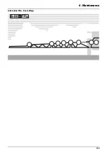
Страница 135: ...6 Maintenance 135 Lubrication Plan Boom Wings 10...

Страница 136: ...Lift There are 4 grease points in each side Central Lubrication The grease nipples are located at the rear of the chassis in both sides Depending on the sprayer setup there can be 0 3 or 4 grease nipp...

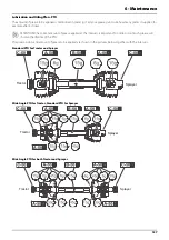
Страница 137: ...the intervals is important Too little or too much grease will shorten the lifetime of the PTO The grease points and amount of grease to be applied are shown in the pictures below together with the int...

Страница 138: ...into each lubrication point A See also the section 50 Hours Service in this book After disassembling the pump diaphragm renewal etc Greasing with 200 grams of grease into each lubrication point A ATTE...

Страница 139: ...ificate or test sticker will then show that the inspected sprayer is approved for future use With a negative result the faults must be rectified to get the approval Check your national rules and guide...

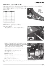
Страница 140: ...it fit between other components on the sprayer Remember to finish off by applying the correct torque NOTE The sealing system for hoses and fittings is ORFS type O Ring Face Seal This ensures a high le...

Страница 141: ...e by turning locks A outwards 4 Clean filter and if necessary clean the housing for larger impurities To Reassemble 1 Grease the O ring on the filter lid 2 Press the filter onto the filter guide lid M...

Страница 142: ...he stop WARNING Always wear protective clothing and gloves before servicing the filter DANGER The pressure SmartValve must always be turned to before opening the CycloneFilter If not the spraying liqu...

Страница 143: ...opening the drain valve 50 Hours Service Greasing the Pump When operating the pump it must be greased every 50 hours with 30 grams of grease into each lubrication point ATTENTION In order to avoid exc...

Страница 144: ...e Over inflated tyres can explode and cause severe injuries WARNING If renewing tyres always use tyres with minimum load index as specified See Tyre Pressure on page 191 50 Hours Service Air Brakes Th...

Страница 145: ...If the rubber parts are worn away the motor will be noisy when rotating and the steel parts will wear out quickly In this case worn parts needs to be replaced as follows 3 Sprayer with high hitch only...

Страница 146: ...er layers 250 Hours Service Wheel Bearings Check for play in the wheel bearings 1 Place chocks in front of and behind the left wheel and jack up the right wheel 2 Support the trailer with axle stands...

Страница 147: ...ub wheel by hand difficult to turn the wheel by hand 5 Turn the nut 60 1 6 turn clockwise to loosen brake Hub wheel should rotate freely now 6 Tighten the brake connector C bolts again 7 Adjust the pa...

Страница 148: ...o vent the right brake cylinder WARNING Always vent the circuit if the hydraulic brake lines have been dismantled 250 Hours Service Air Brake Filters 1 Clean the area around air filter s and disconnec...

Страница 149: ...setting Tighten all bolts to half the specified torque at first then tighten to the full specified torque 15 Tighten again after 10 hours of work Check the torque every day until it is stabilised ATTE...

Страница 150: ...ten the anchor bolt castle nut F again and fit a new cotter pin G 14 Check roller bearings for discolouration and wear Replace if worn or damaged 15 Assemble drum D and bearings E using a new sealing...

Страница 151: ...in doubt contact your local HARDI dealer Lifting and Removing the Pump When lifting and removing the pump use a shackle fitted to the built in lifting eye located between the heads A WARNING To preven...

Страница 152: ...m of the pump is not blocked 9 Apply a small amount of pump grease on the surface between diaphragm washer 6 and diaphragm 7 10 Reassemble the pump with the following torque setting Diaphragm head bol...

Страница 153: ...k the state of the black O ring A 4 Assemble the parts again and tighten with a torque of 1 Nm ATTENTION If any part is worn or damaged it should be replaced Speed Transducer for the Pump The speed tr...

Страница 154: ...ole down through the drain valve hole until it is free in the top of the tank 3 The pole can now be taken out of the tank through the filling hole DANGER Do not enter the tank inside the parts can be...

Страница 155: ...Assembly If leaks of fluid occur in the nozzle holders on the spray boom it is necessary to check the sealing The nozzle holder need to be disassembled to locate the gaskets Occasional maintenance of...

Страница 156: ...ver as shown and pull to remove the upper part C of the nozzle holder Here the locking piece B and the upper part are separated C 4 Inside the lower part D the O ring E is located 5 Check condition an...

Страница 157: ...heck the sealing The pipe fitting need to be disassembled to locate the O ring gasket Occasional maintenance of the O rings gaskets and pipe assemblies is recommended Poor sealing are usually caused b...

Страница 158: ...Remove Lock Ring If the lock ring needs to be replaced the old one can be removed the following way 1 Fit a union nut A in reverse direction 2 Push the union nut A over the lock ring D 3 Place the un...

Страница 159: ...work perfectly over time it is good practice to regularly provoke opening of the safety valve This prevents clogging and ensures proper function of the safety valve Opening of the valve is done by tur...

Страница 160: ...centre section as a minimum as this is the heaviest boom part up to 1000 kg DANGER No one is allowed under the boom while the adjustment is carried out ATTENTION Boom sections that are not supported...

Страница 161: ...Locking Device The trapeze structure in the boom centre helps the boom to stay horizontal when unfolded protects the boom against vibrations and impacts In order to lock the boom during folding the ch...

Страница 162: ...the lock nuts A 2 Adjust the screws B 3 Tighten the lock nuts A 4 Fold the boom to see if it hits and rests correctly in the transport brackets Vertical Alignment of the Inner Wing and Outer Wing ATTE...

Страница 163: ...half It is important to adjust the eccentric bolts simultaneously and in same direction 5 Tighten the nuts A and C again after alignment 6 Fold the boom to see if it hits and rests correctly in the tr...

Страница 164: ...a hand The force is adjusted by the length of the turnbuckle C below the lock bracket B Adjust the turnbuckle C in steps of approximately a quarter turn until the lock force is correct 5 Mount the cy...

Страница 165: ...position half the folding procedure 14 Adjust the cylinder stop E so that it is just touching the cylinder housing Boom Wings Forward The boom wings are adjusted from factory to tip a little forward...

Страница 166: ...res B and C The boom tip should be just visible if correctly adjusted 4 If you do not see the boom tip or you see the most of the boom wing go to step 5 for adjustment Adjustment The black disc D is p...

Страница 167: ...areful not to overtighten or squeeze the rubber bushings B Only tighten until there is no more play Retightening the Chassis The chassis consists of two sections bolted together Also the drawbar is bo...

Страница 168: ...s loose their efficiency they should be replaced 1 Connect the sprayer to a tractor to prevent overbalancing 2 Lift the rear end of the sprayer with e g a crane Use lifting points as described in Spra...

Страница 169: ...e Always use new tubes of recommended size When fitting new tyres always fit new tubes Do not use tubes for tubeless tyres Before mounting always lubricate both tyre beads and rim flange with approved...

Страница 170: ...r outer sections 2 4 Boom centre Cylinder for slant motion Venting Procedure Follow these steps to complete the venting Both venting screws or valves A and B are closed to begin with 1 Cylinder piston...

Страница 171: ...h to steer the sprayer from side to side Only persons working on the sprayer is allowed in the moving area of the sprayer IntelliTrack Potentiometer Calibration If the IntelliTrack potentiometer on th...

Страница 172: ...dden places in the liquid system Depending on your winter temperatures use the recommended mixture ratio in the table below Turn on the pump and operate all valves and functions operating units TurboF...

Страница 173: ...ctions marked on the hoses and they are without damages 7 Electric cables to the tractor are intact and connected correctly Cable sheaths are without damage due to wear stretching and rubbing The elec...

Страница 174: ...6 Maintenance 174...

Страница 175: ...essure gauge but it decreases pressure at the nozzles Impurities sucked in by the pump may prevent the valves from closing correctly thus reducing the pump flow A bad reassembly of the pump elements e...

Страница 176: ...on is on Nozzles are worn Check nozzle output Replace nozzles if the deviation in output exceeds 10 Sucking air towards end of tank load Lower pump speed rpm Pressure increasing Pressure filters begin...

Страница 177: ...mp speed rpm Too high vacuum when filling from external source Hose dimension is too small Fit a larger hose to the External Filling Device Too long filling hose Park sprayer closer to the external ta...

Страница 178: ...l Refit springs to parallel position and check potentiometer reading see IntelliTrack Front Potentiometer Calibration Printed Circuit Board PDUBoardItem Number Assigned Sprayer Function Fuse Socket Fu...

Страница 179: ...OR DELTA FORCE with AutoSlant AutoTerrain 26070300 F1 AUX 1 X1004 F2 15 A 28048600 AUX 2 X1007 F3 10 A 28048500 Guest 1 X400 F4 AUX SW 1 X1001 F5 AUX SW 2 X1003 F6 Guest 2 X500 F7 25 A 261605 ECU IO 1...

Страница 180: ...OBUS retrofit kit for tractor 26040600 J03 J04 100 A Cable between tractor battery and ISOBUS connection red wire Early type MEGA Bolt down fuse Early type 26076800 Later type MIDI Bolt down fuse Late...

Страница 181: ...m In case of a power failure it is possible to operate all functions of the operating unit manually Disconnect the power supply to the sprayer Manually turn the control knobs on the distribution valve...

Страница 182: ...7 Fault Finding 182...

Страница 183: ...Width Track Width Track Width Mudguards Clearance Fixed Axle Short Axle Long Axle 270 95 R48 1800 or 2000 mm 1500 2000 mm 1800 2250 mm 345 mm 700 mm 300 95 R46 1800 or 2000 mm 1520 2000 mm 1800 2250...

Страница 184: ...40 85 R48 Tank 3000 litres Tank 4000 litres Empty Tank Full Tank Boom Width Axle Load kg Drawbar Load kg Total Weight kg Axle Load kg Drawbar Load kg Total Weight kg 21 m 3774 150 3924 7156 1418 8574...

Страница 185: ...8 Technical Specifications 185 Pump Specifications Pump Model 464 5 5 Pump Model 464 6 5 Pump Model 464 10 0 Pump Model 464 12 0...

Страница 186: ...s working within giving the actual pump the following approximate performance rates 5 Pump Capacity Testing Testing the pump must be carried out according to the international standard ISO 16122 2 or...

Страница 187: ...from the oil Filtration quotient 25 75 ISO 4572 81 Multipass test Follow the tractor oil change schedule as directed Choose hydraulic oil with anti foam and anti oxidant additives Be especially cautio...

Страница 188: ...ents Power Consumption Recommended tractor engine output are as follows Hydraulic Motor for Liquid Pump Max hydraulic oil pressure 150 bar Min hydraulic oil pressure 120 bar Max hydraulic oil flow 30...

Страница 189: ...eed 1000 RPM The tractor must follow the international standard ISO 500 1 2014 regarding general specifications safety requirements dimensions for mastershieldandclearancezoneforrear mountedpowertake...

Страница 190: ...less residue Airborne Noise Emission Airborne noise emission from operating the sprayer relates to the two defined operator positions in the tractor cab or operating the chemical incorporator filling...

Страница 191: ...f Tyre on page 169 for tyre fitting instructions Speed In Field Speed 25 km h Speed 40 km h Speed 50 km h Tyre Size Load Index Tyre Pressure bar Max Axle Load kg Max Axle Load kg Max Axle Load kg Max...

Страница 192: ...0 B 50 109 1030 146 3000 D 65 110 1060 147 3075 F 80 111 1090 148 3159 J 100 112 1120 149 3250 113 1150 150 3350 114 1180 151 3450 115 1215 152 3550 116 1250 153 3650 117 1285 154 3750 118 1320 155 38...

Страница 193: ...Used Disposal of Cleaning Water Protect the environment When cleaning the sprayer inside and outside dispose of chemical residues in the liquid system and water containing cleaning agent according to...

Страница 194: ...ring loom As the configuration and number of lights may differ between variants of the sprayer specific wiring charts can be obtained separately Contact the HARDI dealer if necessary Position Designat...

Страница 195: ...8 Technical Specifications 195 Hydraulic Diagrams Hydraulics for Boom of 21 24 Meters...

Страница 196: ...8 Technical Specifications 196 Hydraulics for Boom of 27 28 Meters...

Страница 197: ...8 Technical Specifications 197 Hydraulics for Chassis Z version With IntelliTrack Hydraulics for Chassis Z version With ManualTrack...

Страница 198: ...8 Technical Specifications 198...

Страница 199: ...g Speed 82 Pipe clamp 155 Readjustment 160 Re tightening 145 Boom and terminology 64 BoomPrime 60 115 Adjustment 86 One way Valve 153 Brakes 190 Emergency and Parking 92 Hydraulically Activated 92 Byp...

Страница 200: ...Label Explanation 18 Level Indicator 154 Liability 11 Lifetime 48 Light Bulbs 168 Liquid System 49 86 99 Faults 176 Load Apportioning Valve 94 189 Load Sensing 81 Lock mechanism 164 Lubrication 133 Bo...

Страница 201: ...29 Info 97 Informal Measures 21 Normal Operation 23 Operator 76 Personal Protective Equipment 16 Precautions 107 Protection Equipment 20 Symbols 17 Valve 159 SafetyLocker 69 Sensors Speed 85 Service...

Страница 202: ...0 Closed Centre Hydraulics 81 Open Centre Hydraulics 81 Pressure Regulation 50 TurboDeflector 108 TurboFiller Suction 108 Valves Symbols 51 View 43 44 VPZ boom 64 W Weight 184 Wheel Bearings 146 Dimen...

Страница 203: ...he menu on the left 3 Select Spare parts catalogue and find your spare part 4 Online ordering is also possible 5 Contact your HARDI dealer for further information on spare parts User Evaluation Dear R...

Страница 204: ...HARDI INTERNATIONAL A S Herthadalvej 10 DK 4840 N rre Alslev DENMARK...

Отзывы: