


4 - Sprayer setup
45
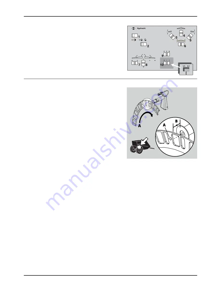
Label for Manually Steered Version (optional)
When having a manually steered sprayer version, there are no hydraulic
controls for the steering at the hydraulic control unit. To control the
steering, one of the optional switches (10) on the hydraulic control unit
is used.
•
Place the “Manual steering” label (part no. 72547600) on the
control unit at the sign originally meant for optional function (10).
Speed Transducer for Sprayer
The speed transducer and speed ring are located at the inside of the
sprayers right wheel. The sensor is an inductive type that requires a
metallic protrusion like a speed ring to pass by it to trigger a signal.
Adjustment
1.
Assure that the speed ring is correctly fitted to the wheel, so that
the arrow (A) follows the forward rotation of the wheel.
2.
Adjust so the sensor lines up in the middle of the gaps in vertical
direction. Distance from centre of the sensor to top of the brake
drum:
•
412 mm brake drum = 60 mm
•
400 mm brake drum = 75 mm
μ
ATTENTION! If necessary, readjust plate on the axle.
3.
Adjust air gap (B) to 3 - 6 mm. Use a feeler gauge or similar tool.
÷
NOTE! Adjustment shall be made out of one of the carriage bolts for the speed ring.
4.
After adjustment then spin up the wheel. Verify air gap variation less than +/-0.5 mm. Check this at the entire
circumference.
5.
Verify speed at the controller.
μ
ATTENTION! Correct fitting is indicated by continuous flashing from transducer, when the wheel rotates.
Содержание NAVIGATOR FORCE
Страница 4: ...1 EU Declaration 4 ...
Страница 12: ...2 Safety Notes 12 ...
Страница 54: ...4 Sprayer setup 54 ...
Страница 76: ...6 Maintenance 76 Boom lubrication oiling plan ...
Страница 112: ...8 Technical specifications 112 ...
Страница 116: ...Index 116 ...
Страница 118: ...HARDI INTERNATIONAL A S Herthadalvej 10 DK 4840 Nørre Alslev DENMARK ...


