background image

18

The distributor warrants this fan to be free from defects in workmanship and materials present at time 
of shipment from the factory for Lifetime limited from the date of purchase.  This warranty applies only 
to the original purchaser. The distributor agrees to correct any defect at no charge or, at our option, 
replace the ceiling fan with a comparable or superior model.
   
To obtain warranty service, present a copy of your sales receipt as proof of purchase.  All cost of 
removal and reinstallation are the express responsibility of the purchaser.  Any damage to the ceiling 
fan by accident, misuse or improper installation, or by using parts not produced by the manufacturer 
of this fan or affixing accessories not produced by the manufacturer of this fan, are the purchaser's 
own responsibility.  The distributor assumes no responsibility whatsoever for fan installation during the 
limited lifetime warranty.  Any service performed by an unauthorized person will render the warranty 
invalid.
 
Due to varying climatic conditions, this warranty does not cover changes in brass finish, rusting, 
pitting, tarnishing, corroding or peeling.  Brass finish fans maintain their beauty when protected from 
varying weather conditions.  Any glass provided with this fan is not covered by the warranty.
 
Any replacement of defective parts for the ceiling fan must be reported within the first year from the 
date of purchase.  For the balance of the warranty, call our customer service department 
(

at 

1-800-643-0067

)

 for return authorization and shipping instructions so that we may repair or replace 

the ceiling fan.  Any fan or parts returned improperly packaged is/are the sole responsibility of the 
purchaser.  There is no further express warranty.  The distributor disclaims any and all implied 
warranties.  The duration of any implied warranty which cannot be disclaimed is limited to the limited 
lifetime period as specified in our warranty.  The distributor shall not be liable for incidental, 
consequential or special damages arising at or in connection with product use or performance except 
as may otherwise be accorded by law.  This warranty gives you specific legal rights and you may also 
have other rights which vary from state to state and province to province.  This warranty supersedes 
all prior warranties.

LIMITED LIFETIME WARRANTY

KHLI1909

Printed in China

REPLACEMENT PARTS LIST

For replacement parts, call our customer service department at 

1-800-643-0067

, 8 a.m. - 8 p.m., EST, 

Monday - Sunday.

A

D

G

J

 PART           DESCRIPTION

  #0888716/61035000       #0888715/61035001     #0888714

             PART #                            PART #                 PART #

 A  Mounting 

Bracket


Light Kit Fitter

 G  Blade
 J  Blade 

Arm

0888716-A/61035000-A
0888716-D/61035000-D
0888716-G/61035000-G
0888716-J/61035000-J

0888715-A/61035001-A
0888715-D/61035001-D
0888715-G/61035001-G
0888715-J/61035001-J

0888714-A
0888714-D
0888714-G
0888714-J

Содержание C-BTH44ABZC5L

Страница 1: ...BTH44BNK5L C BTH44WW5L Questions problems missing parts Before returning to your retailer call our customer service department at 1 800 643 0067 8 a m 8 p m EST Monday Sunday Purchase Date PH19437 1 ITEM 0888716 61035000 0888715 61035001 0888714 Français p 19 4009654 ATTACH YOUR RECEIPT HERE JOIGNEZ VOTRE REÇU ICI ...

Страница 2: ...999 Hire a qualified electrician or consult a do it yourself wiring handbook if you are unfamiliar with installing electrical wiring Make sure the installation site you choose allows a minimum clearance of 7 ft from the blades to the floor and at least 30 in from the end of the blades to any obstruction After you install the fan make sure all connections are secure to prevent the fan from falling ...

Страница 3: ... fan lead wires consult an electrician for the proper size wire connectors to use To reduce the risk of fire or electrical shock do not use the fan with any solid state speed control device or control fan speed with a full range dimmer switch To reduce the risk of fire electrical shock or personal injury do not bend the blade arms when installing them balancing the blades or cleaning the fan Do no...

Страница 4: ...ions may cause harmful interference to radio communications However there is no guarantee that interference will not occur in a particular installation If this equipment does cause harmful interference to radio or television reception which can be determined by turning the equipment off and on the user is encouraged to try to correct the interference by one or more of the following measures Reorie...

Страница 5: ...tor Housing Lock 4 Washer preassembled S Mounting Bracket Nut 4 preassembled T Rubber Washer 1 preassembled U Safety Cable 1 preassembled V Vice preassembled 1 W Motor Screw 10 preassembled 1 extra X 14 mm Hex Nut 1 preassembled PART DESCRIPTION QUANTITY A Mounting Bracket 1 B Motor Housing 1 C Motor Assembly 1 D Light Kit Fitter 1 E Glass Shade 1 F Pull Chain Extension 2 G Blade 5 H Finial Plate ...

Страница 6: ...ver Pliers Safety Glasses Stepladder and Wire Strippers Helpful Tools not included AC Tester Light Tape Measure Do It Yourself Wiring Handbook and Wire Cutters HARDWARE CONTENTS shown actual size PREPARATION CC Blade Screw Qty 15 1 extra Wire Connector Qty 4 BB AA Fiber Blade Washer Qty 15 1 extra Turn off circuit breakers and wall switch to the fan supply line leads DANGER Failure to disconnect p...

Страница 7: ...ll mounting bracket nuts S and mounting bracket flat washers Q from mounting bracket A 3 INITIAL INSTALLATION 3 A S Q 2 7 ft min 30 in min G Secure mounting bracket A to outlet box not included using screws spring washers and flat washers provided with the outlet box NOTE It is very important you use the proper hardware when installing the mounting bracket A as this will support the fan 4 4 A ...

Страница 8: ...s W and lock washers N discard the plastic motor blocks 6 C J Hook Bar A Small Hole End Bar 1 Adjust the length of the safety cable U preassembled to the bar on motor assembly C by loosening screw and nut on the vice V and pulling on the safety cable U Adjust slack in safety cable U to a hand s length and re tighten screw and nut on vice V securely The loop at the end of the safety cable U should ...

Страница 9: ...s as follows NOTE For each wire connection below use one of the wire connectors CC making sure to screw wire connector CC on in a clockwise direction 1a FAN AND LIGHT CONTROLLED BY PULL CHAINS Connect BLACK and BLUE wire from fan to BLACK wire from ceiling Connect WHITE wire from fan to WHITE wire from ceiling Connect all GROUND GREEN wires together from fan on motor assembly C and mounting bracke...

Страница 10: ...ontrol the fan and light with separate wall switches connect BLACK wire from fan to BLACK wire from the independent wall switch for the fan Connect BLUE wire from fan to the BLACK wire from the other independent wall switch for the light Connect WHITE wire from fan to WHITE wire from ceiling Connect all GROUND GREEN wires together from fan on motor assembly C and mounting bracket A to BARE GREEN w...

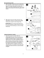
Страница 11: ...hers R Slide motor housing B over motor assembly C aligning slotted holes in motor housing B with loosened motor housing mounting screws O in mounting bracket A Twist motor housing B to lock Re insert the other two motor housing mounting screws O along with motor housing lock washers R previously removed Tighten all motor housing mounting screws O securely 3 DANGER To reduce the risk of serious bo...

Страница 12: ... 14 mm hex nut X and rubber washer T from bottom of light kit fitter D Save hardware for later use 5 Threaded Rod Switch Housing Cap Locate BLUE or BLACK and WHITE wires in switch housing of motor assembly C labeled FOR LIGHT and remove plastic that holds these two wires together Also remove molex safety caps from bottom of BLUE or BLACK and WHITE wires NOTE It may be necessary to pull firmly in o...

Страница 13: ...late H and finial I that were previously removed Step 5 page 12 Place rubber washer T inside glass shade E over center hole Align hole in center of glass shade E with threaded rod on light kit fitter D allowing pull chains to come through corresponding holes in glass shade E Push up gently on glass shade E until threaded rod comes through hole Be sure fan pull chain will not rub against bulbs duri...

Страница 14: ...NING RISK OF SHOCK The molex safety caps should not be removed unless a light kit will be immediately installed and the power should be turned off prior to molex safety cap removal and light kit installation 11 11 12 12 Place cap DD firmly in hole in middle of switch housing cap Align holes in switch housing cap with holes in switch housing of motor assembly C Make sure to align gap on top edge of...

Страница 15: ...cluded to the fan pull chain OPERATING INSTRUCTIONS Switch Housing The pull chain located on the switch housing has four positions to control fan speed One pull is HIGH two is MEDIUM three is LOW and four turns the fan OFF 1 The pull chain located in the center is used to turn the light ON or OFF 2 1 2 ...

Страница 16: ...erse switch 3 Switch Housing OPERATING INSTRUCTIONS 3a 3b 3c 3c IMPORTANT Reverse switch must be set either completely UP or completely DOWN for fan to function If the reverse switch is set in the middle position fan will not operate 3a In warmer weather setting the reverse switch in the DOWN position will result in downward airflow creating a wind chill effect 3b In cooler weather setting the rev...

Страница 17: ...ch 4 Fan is new 5 Motor housing is loose 1 Tighten all blade screws 2 Replace blade 3 Replace with an approved speed control device 4 Allow fan a break in period of a few days especially when running the fan at Medium and High speeds 5 Turn power off Carefully loosen motor housing and verify mounting bracket is secure according to instructions on page 11 Excessive wobbling 1 Blades are loose 2 Bla...

Страница 18: ...rts for the ceiling fan must be reported within the first year from the date of purchase For the balance of the warranty call our customer service department at 1 800 643 0067 for return authorization and shipping instructions so that we may repair or replace the ceiling fan Any fan or parts returned improperly packaged is are the sole responsibility of the purchaser There is no further express wa...

Страница 19: ...5L C BTH44BNK5L C BTH44WW5L Des questions des problèmes des pièces manquantes Avant de retourner l article au détaillant appelez notre service à la clientèle au 1 800 643 0067 entre 8 h et 20 h HNE du lundi au dimanche JOIGNEZ VOTRE REÇU ICI Numéro de série Date d achat 19 ARTICLE 0888716 61035000 0888715 61035001 0888714 4009654 ...

Страница 20: ...ssurez vous que tous les raccords sont bien fixés pour éviter que le ventilateur ne tombe Le poids net de ce ventilateur y compris l ensemble de luminaire est de 5 9 kg DANGER Si vous utilisez une boîte de sortie existante assurez vous qu elle est fixée solidement à la structure de l immeuble et qu elle sera en mesure de supporter tout le poids du ventilateur La non observance de cette consigne pe...

Страница 21: ...entilateur consultez un électricien pour déterminer la taille des capuchons de connexion à utiliser Afin de réduire les risques d incendie ou de choc électrique n utilisez pas ce ventilateur avec un appareil électronique de réglage de vitesse ni avec un gradateur pleine bande Afin de réduire les risques d incendie de choc électrique ou de blessure ne pliez pas les fixations des pales lors de leur ...

Страница 22: ... instructions risque de provoquer des interférences nuisibles aux communications radio Cependant tout risque d interférence ne peut être totalement exclu S il constate des interférences lors de la réception d émissions de radio ou de télévision il suffit pour le vérifier d allumer et d éteindre successivement l appareil l utilisateur devra prendre les mesures nécessaires pour les éliminer À cette ...

Страница 23: ...de fixation préassemblé 4 T Rondelle en caoutchouc préassemblée 1 U Câble de sécurité préassemblé 1 V Étau préassemblé 1 W Vis de moteur 10 préassemblée 1 en surplus X Écrou hexagonal de 14 mm 1 préassemblé PIÈCE DESCRIPTION QUANTITÉ A Support de fixation 1 B Boîtier de moteur 1 C Ensemble de moteur 1 D Dispositif de fixation de 1 l ensemble de luminaire E Abat jour en verre 1 F Rallonge de chaîne...

Страница 24: ...abeau et pinces à dénuder Outils utiles non inclus détecteur de tension c a ruban à mesurer guide de câblage pour bricoleurs et coupe fil QUINCAILLERIE INCLUSE grandeur réelle PRÉPARATION CC Vis de pale Qté 15 1 en surplus Capuchon de connexion Qté 4 BB AA Rondelle de pale en fibre Qté 15 1 en surplus Coupez l alimentation électrique à partir du panneau de disjoncteurs et à l aide de l interrupteu...

Страница 25: ...us S et les rondelles plates Q du support de fixation A 3 INSTALLATION INITIALE 2 2 13 m min 76 2 cm min G Fixez le support de fixation A à la boîte de sortie non incluse à l aide des vis des rondelles à ressort et des rondelles plates fournies avec la boîte de sortie REMARQUE Il est très important d utiliser la quincaillerie appropriée lorsque vous installez le support de fixation A car il soutie...

Страница 26: ... moteur W et aux rondelles de blocage N jetez les 6 C Crochet en J Barre A Petit trou Extrémité de la barre 1 Réglez la longueur du câble de sécurité U préassemblé à la barre de l ensemble de moteur C en desserrant la vis et l écrou de l étau V tout en tirant sur le câble U Laissez un jeu équivalant à la longueur d une main et resserrez fermement la vis et l écrou de l étau V La boucle située à l ...

Страница 27: ...ts appropriés en suivant les instructions ci dessous REMARQUE Pour chacun des branchements indiqués ci dessous utilisez l un des capuchons de connexion CC Assurez vous de visser les capuchons de connexion CC dans le sens des aiguilles d une montre 1a VENTILATEUR ET LUMINAIRE COMMANDÉS PAR DES CHAÎNES raccordez le fil NOIR et BLEU du ventilateur au fil NOIR du plafond Raccordez le fil BLANC du vent...

Страница 28: ...COMMANDÉS PAR DEUX INTERRUPTEURS MURAUX si vous comptez commander le ventilateur et le luminaire à l aide d interrupteurs muraux distincts raccordez le fil NOIR du ventilateur au fil NOIR de l interrupteur mural utilisé pour le ventilateur Raccordez le fil BLEU du ventilateur au fil NOIR de l autre interrupteur mural utilisé pour le luminaire Raccordez le fil BLANC du ventilateur au fil BLANC du p...

Страница 29: ...de moteur C et alignez les fentes du boîtier de moteur B aux vis de montage du boîtier de moteur O desserrées du support de fixation A Vissez le boîtier de moteur B pour le verrouiller en place Remettez en place les deux autres vis de montage du boîtier de moteur O et les rondelles de blocage du boîtier de moteur R retirées précédemment Serrez fermement toutes les vis de montage du boîtier de mote...

Страница 30: ...spositif de fixation de l ensemble de luminaire D Mettez de côté la quincaillerie pour une utilisation ultérieure 5 Repérez les fils BLEU ou NOIR et BLANC du boîtier de l interrupteur de l ensemble de moteur C portant l indication FOR LIGHT pour le luminaire et retirez l enveloppe en plastique qui maintient ces deux fils ensemble Retirez également les capuchons de sécurité Molex de l extrémité inf...

Страница 31: ...30 Placez la rondelle en caoutchouc T sur le trou central à l intérieur de l abat jour en verre E Alignez le trou central de l abat jour en verre E avec la tige filetée du dispositif de fixation de l ensemble de luminaire D en prenant soin de faire passer les chaînes dans les trous correspondants de l abat jour en verre E Poussez l abat jour en verre E délicatement vers le haut jusqu à ce que la t...

Страница 32: ...LATION DÉFINITIVE 10 Pour le ventilateur Pour le luminaire Fixez les rallonges de chaîne F fournies ou des rallonges de chaîne de votre choix non incluses aux chaînes du ventilateur et du luminaire L assemblage est terminé 10 F 11 12 Insérez fermement le capuchon DD dans le trou central du couvercle du boîtier de l interrupteur Alignez les trous du couvercle du boîtier de l interrupteur à ceux du ...

Страница 33: ... MODE D EMPLOI Boîtier de l interrupteur La chaîne du boîtier de l interrupteur offre quatre réglages de la vitesse du ventilateur Tirez une fois pour une vitesse ÉLEVÉE deux fois pour une vitesse MOYENNE trois fois pour une vitesse FAIBLE et quatre fois pour ÉTEINDRE le ventilateur 1 La chaîne du milieu permet d ALLUMER et d ÉTEINDRE la lumière 2 1 2 ...

Страница 34: ... 3a 3b 3c IMPORTANT L interrupteur d inversion doit être réglé complètement vers le HAUT ou complètement vers le BAS pour que le ventilateur fonctionne Si vous réglez l interrupteur d inversion à la position centrale le ventilateur ne fonctionnera pas 3a Lorsque les températures sont chaudes vous pouvez régler l interrupteur d inversion vers le BAS pour orienter le débit d air vers le bas et ainsi...

Страница 35: ... 1 Réglez l interrupteur complètement vers le haut ou le bas 2 Rétablissez l alimentation électrique ou vérifiez le fusible 3 Coupez l alimentation électrique Défaites le boîtier de moteur et vérifiez toutes les connexions L appareil fonctionne bruyamment 1 Les pales sont desserrées 2 Une pale est fissurée 3 Vous utilisez un gradateur pleine bande 4 Le ventilateur est neuf 5 Le boîtier de moteur e...

Страница 36: ...te l utilisation de pièces non produites par le fabricant du ventilateur ou l ajout d accessoires non couverts par cette garantie Le distributeur n est aucunement responsable de l installation du ventilateur durant la période de garantie à vie limitée Toute réparation effectuée par une personne non autorisée annulera la garantie Étant donné les conditions climatiques variables cette garantie ne co...

Страница 37: ...notre service à la clientèle au 1 800 643 0067 entre 8 h et 20 h HNE du lundi au dimanche A D G J PIÈCE DESCRIPTION 0888716 61035000 0888715 61035001 0888714 No DE PIÈCE No DE PIÈCE No DE PIÈCE 0888716 A 61035000 A 0888716 D 61035000 D 0888716 G 61035000 G 0888716 J 61035000 J 0888715 A 61035001 A 0888715 D 61035001 D 0888715 G 61035001 G 0888715 J 61035001 J 0888714 A 0888714 D 0888714 G 0888714 ...

Отзывы: