installation & connection
20_
installation & connection
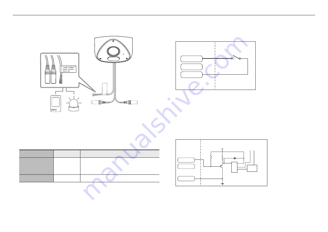
Connecting to the I/O port box
Connect the Alarm I/O cable to the corresponding port of the port box.
Sensor
Alarm
Alarm-related Connector
J
`
Make sure to connect the provided audio/alarm cable before use.
Color
Function
Description
ORANGE : ALARM #1
BROWN : ALARM #2
ALARM I/O 1,
ALARM I/O 2
These two ports are configurable from the web viewer, as they can be
used as Alarm in or Alarm out
※
Alarm I/O changes can be made through the Webviewer setup.
BLACK
GND
It is a ground terminal.
To connect to an external sensor
To use as an Alarm IN: Connect one of the [
ALARM I/O
] port and the other terminal to the [
GND
] port.
Alarm In Wiring Diagram(example)
Sensor
External connection
ALARM #1
ALARM #2
GND
Alarm cable
<If ALARM I/O 1 is set as an input terminal>
To connect to an alarm output
If devices (e.g., flashing light and siren) that exceed the voltage and current specifications are connected by
using the open collector method, it may cause damage.
Refer to the alarm out connection diagram below case.
Alarm Out Wiring Diagram(example)
ALARM
POWER
ALARM
RESISTOR
DIODE
RELAY
VCC
GND
TRANSISTOR
External connection
Alarm cable
ALARM #1
ALARM #2
GND
<If ALARM I/O 1 is set as an output terminal>
Содержание TNV-C7013RC
Страница 1: ...NETWORK CAMERA User Manual TNV C7013RC...
Страница 30: ......


