background image


Section 5  


Hydraulic 

Spinners 


Содержание PT-6 FSS

Страница 1: ...Model PT 6 FSS Fertilizer and Lime Spreader SERIAL __________________ WORK ORDER ___________...

Страница 2: ......

Страница 3: ...Page S 6 Safety Decals Page S 7 PTO Shaft Adjustment and Maintenance How to Shorten the PTO Shaft Page P 1 Proper Lubrication Page P 2 Section 1 Basic Information PT 6 FSS PT 6 FSS Height and Length P...

Страница 4: ...draulic Cylinder Engagement Assembly Page 3 4 Hydraulic Cylinder Engagement Assembly Parts List Page 3 5 Section 4 Hydraulic Spinners with Press Wheel Drive Hydraulic Spinners Plug to Tractor Page 4 1...

Страница 5: ...er Rotation Page 5 9 Setting Spinner Speed Page 5 10 Section 6 Flow Divider Assembly Flow Divider Parts Breakdown Page 6 1 Flow Divider Parts List Page 6 2 Section 7 Axles Tires 6 Bolt Hub Assembly Ex...

Страница 6: ...ustment Spread Pattern Adjustment Page 10 1 Spread Pattern Adjustment Spinners and Flow Divider Page 10 2 Spread Pattern Adjustment Preparation and Procedure Page 10 3 Spread Pattern Adjustment Data R...

Страница 7: ...Johnson Accounts Receivable Collections Michael Sosebee Sales Manager Gene Dye Outside Sales Mid South Regional Sales Dan McCorvey Outside Sales Southeast Regional Sales Richard Wray Outside Sales Wes...

Страница 8: ......

Страница 9: ...LL COST C Warranty Claim Forms Dealer Only a Warranty claim form forms will be supplied to Dealer upon request b Warranty claim forms are available in 2 part paper form or in an electronic format c Al...

Страница 10: ...ext Day Air will be the sole responsibility of the Customer Dealer H Parts Returns a All parts replaced under warranty will be returned to Chandler Equipment Company within 20 days of replacement for...

Страница 11: ...Company accepts no responsibility nor shall warrant any equipment or any component that is damaged due to any type Control System not sold and installed by Chandler Equipment Company K Items Not Cove...

Страница 12: ......

Страница 13: ...Fertilizer and Lime Spreader Safety...

Страница 14: ...A safety label alerts you of potential hazards that can injure you or others Each safety label is preceded by a safety alert symbol and either the words DANGER WARNING or CAUTION DANGER Failure to fo...

Страница 15: ...ing parts when spreader is in operation 3 Check lug nuts daily 4 Maintain proper tire pressure according tire manufacturers specifications 5 If spreader becomes clogged turn off PTO Hydraulics before...

Страница 16: ...cals WARNING DO NOT ADJUST UNTIL SPINNERS STOP MOVING STAY OUT OF BOX WHILE CONVEYOR IS IN MOTION DO NOT RIDE ON SPREADER WHILE VEHICLE IS IN MOTION STAY CLEAR OF SPINNERS WHILE SPINNERS ARE IN MOTION...

Страница 17: ...S 4 PTO SAFETY DECAL...

Страница 18: ...S 5 LUG NUT DECAL MAXIMUM LOADED SPEED MAKE SURE TO CHECK LUG NUTS DAILY CAUTION WARNING DO NOT EXCEED 25 MPH...

Страница 19: ...S 6 HYDRAULIC SYSTEM DECAL...

Страница 20: ...S 7 ROTATING CHAIN WARNING ROTATING SPINNERS WARNING...

Страница 21: ...PTO Shaft Adjustment And Maintenance...

Страница 22: ...at this point without bottoming out no further action is necessary 2 If the driveline will not fit without bottoming out separate the driveline into two half shafts Mount the tractor half on the PTO a...

Страница 23: ...f the driveline and manually lubricate the telescoping tubes Check that all components are in good condition and properly lubricated before using the driveline Clean and re lubricate the driveline bef...

Страница 24: ......

Страница 25: ...Section 1 Basic Information...

Страница 26: ...1 1 6PT FSS...

Страница 27: ...1 2...

Страница 28: ...1 3 Fertilizer 65 Lime 90 Hopper Capacity 56 Cubic Ft 56 Cubic Ft Payload 3 640 Lbs 4 000 Lbs CAUTION 2 TON MAXIMUM CAPACITY DO NOT OVERLOAD...

Страница 29: ...Section 2 PTO Drive Spinners...

Страница 30: ...2 1 A C B D C E F1 G C H I J I F2 L M N O S T C V P R C C PTO DRIVEN SPINNERS BASIC PARTS ILLUSTRATION DRIVELINE SHOWN W UNISHEILD TELESCOPING TYPE K Q W C...

Страница 31: ...G 1100 2 204 2 B 8 6 SK Pulley 540 PTO 1100 2 216 1 1 4 SK Bushing 1100 2 199 2 B 11 0 SK Pulley 1000 PTO 1100 2 216 1 1 4 SK Bushing H 200 2 023 PTO Drive Line 1 1 4 Shaft Specify Length I 200 2 002...

Страница 32: ...sc Only 7 Ga Mild Steel R H 300 FL 102 R 24 Spinner Disc Only S S R H V 300 1 208 Spacer Lock Collar for 1 1 4 Shaft W UCF 207 20 1 1 4 4 Bolt Flange Bearing 300 1 126 Front Belt Guard 540 PTO 300 1 1...

Страница 33: ...2 4...

Страница 34: ...4 Bolt Fan Hub E 300 1 207 Fan Shaft 33 F UCF 208 24 1 1 2 4 Bolt Flange Bearing G 700 1 109 60 BS 30 X 1 1 2 Sprocket H 700 1 111 60 BS 40 X 1 1 2 Sprocket I 200 2 042 Key 3 8 X 1 1 2 J 700 1 121 60...

Страница 35: ...necting Pin 500 3 309 24 S S Connecting Pin U 1100 2 201 2 B 4 4 SH Pulley V 1100 2 202 2 B 5 6 SDS Pulley W 1100 1 105 B 62 V Belt X 1100 1 102 B 39 V Belt Y PTF 71 2RZ PTF Spinner Gear Case Z UCF 20...

Страница 36: ...2 7 Hydraulic Cylinder Engagement Assembly...

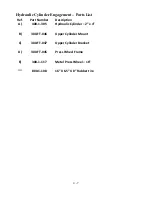
Страница 37: ...Part Number Description A 400 1 305 Hydraulic Cylinder 2 x 4 B 300 FT 046 Upper Cylinder Mount C 300 FT 047 Upper Adjustable Cylinder Bracket D 300 FT 045 Press Wheel Frame E 300 1 117 Metal Press Wh...

Страница 38: ......

Страница 39: ...PTF 71 2 RZ PTO Drive Spinner Gear Case Assembly and Parts List...

Страница 40: ...Po ck this beo ring with greo se o t o sser bly Olllllllillg PTF 71 2RZ Spinner Gear Case Note Bevel Gear 17 goes on Input Shaft side for PTO Drive Spinner PTF 71 2RZ 2 9...

Страница 41: ...11 Oil Seal 4 8 PTF 12 Retaining Ring 4 9 PTF 10R Race Bearing 4 10 PTF 10C Cone Bearing 4 11 PTF 16 Thrust Washer 4 12 PTF 13 Retaining Ring 2 13 PTF 8P Pinion 1 14 PTF 18A Shim 0 005 2 15 PTF 9 Pin...

Страница 42: ...ug PTF 71 2 RZ Gear Case Oil Level and Grease Point Vent Recommended 90W Gear Lubricant Check Gear Lube before using Upper housing is factory greased but should Daily when in operation 2 3 pumps with...

Страница 43: ...Section 3 Full Press Wheel Drive Assembly...

Страница 44: ...3 1...

Страница 45: ...ulley 1100 2 216 1 1 4 SK Bushing M 1100 2 202 2 B 5 6 SDS Pulley 1100 2 215 1 1 4 SDS Bushing N 1100 2 201 2 B 4 4 SH Pulley 1100 2 214 1 1 4 SH Bushing O 1100 2 203 4 B 4 4 SD Pulley 1100 2 213 1 1...

Страница 46: ...nner Disc Only S S L H 7 300 FL 101 R 24 Spinner Disc Only 7 Ga Mild Steel R H 300 FL 102 R 24 Spinner Disc Only S S R H 8 300 FL 112 4 Bolt Fan Hub 9 300 FL 107 L F L Spinner Blade Mild Steel L H 300...

Страница 47: ...3 4...

Страница 48: ...3 5...

Страница 49: ...3 6 Hydraulic Cylinder Engagement Assembly...

Страница 50: ...st Ref Part Number Description A 400 1 305 Hydraulic Cylinder 2 x 4 B 300 FT 046 Upper Cylinder Mount C 300 FT 047 Upper Cylinder Bracket D 300 FT 045 Press Wheel Frame E 300 1 117 Metal Press Wheel 1...

Страница 51: ...PTF 71 2 RZ FP Full Press Wheel Drive Spinner Gear Case Assembly and Parts List...

Страница 52: ...Po ck this loeo ring with greo se o t o sseMloly 12 PTF 71 2RZ FP Spinner Gear Case Note Bevel Gear 17 goes on the opposite side from Input Shaft for Full Press Wheel Drive Spinners PTF 71 2RZ FP 3 8...

Страница 53: ...il Seal 4 8 PTF 12 Retaining Ring 4 9 PTF 10R Race Bearing 4 10 PTF 10C Cone Bearing 4 11 PTF 16 Thrust Washer 4 12 PTF 13 Retaining Ring 2 13 PTF 8P Pinion 1 14 PTF 18A Shim 0 005 2 15 PTF 9 Pin 2 16...

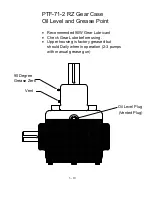
Страница 54: ...ug PTF 71 2 RZ Gear Case Oil Level and Grease Point Vent Recommended 90W Gear Lubricant Check Gear Lube before using Upper housing is factory greased but should Daily when in operation 2 3 pumps with...

Страница 55: ...Section 4 Press Wheel for Plug to Tractor Hydraulic Spinners...

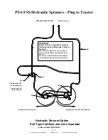
Страница 56: ...wise Right Spinner turns Counter Clockwise D A B Turn Ball Valve OFF for Closed System Turn Ball Valve ON for Open System WARNING Failure to hook up Hydraulic Spinner Option properly will Damage Tract...

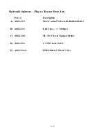
Страница 57: ...to Tractor Parts List Part Description A 400 1 313 Flow Control Valve with Built in Relief B 400 1 323 Ball Valve 3000psi C 400 C 201 M 30 2 Gear Spinner Motor D 400 1 316 LT 50 Check Valve E 400 1 31...

Страница 58: ...4 3...

Страница 59: ...S Connecting Pin 500 3 308 20 S S Connecting Pin 500 3 309 24 S S Connecting Pin M PTWC 16 415 Rear Roller Assemble 16 Chain PTWC 20 415 Rear Roller Assemble 20 Chain PTWC 24 415 Rear Roller Assemble...

Страница 60: ...L Spinner Blade S S R H S 300 FT 038A S 1 1 4 GW Shaft 14 T 300 FT 038 L 1 1 4 GW Shaft U UCF 207 20 1 1 4 4 Bolt Flange Bearing V 300 1 214 AFC Motor Mount Mild Steel 300 1 214A AFC Motor Mount Stain...

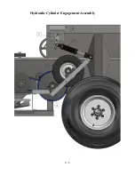
Страница 61: ...4 6 Hydraulic Cylinder Engagement Assembly...

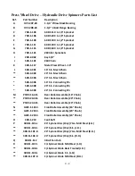
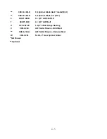
Страница 62: ...List Ref Part Number Description A 400 1 305 Hydraulic Cylinder 2 x 4 B 300 FT 046 Upper Cylinder Mount C 300 FT 047 Upper Cylinder Bracket D 300 FT 045 Press Wheel Frame E 300 1 117 Metal Press Whee...

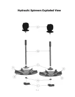
Страница 63: ...Section 5 Hydraulic Spinners...

Страница 64: ...5 1...

Страница 65: ...L H 300 FL 102 L 24 Spinner Disc Only S S L H E 300 FL 101 R 24 Spinner Disc Only 7 Ga Mild Steel R H 300 FL 102 R 24 Spinner Disc Only S S R H F 300 FL 107 L F L Spinner Blade Mild Steel L H 300 FL 1...

Страница 66: ...00 C 205 4 2 BOLT B SHAFT END COVER SEC 8 ROLLER BEARING 400 C 204 5 PIPE PLUG 1 4 NPT FOR SEC 9 THRUST PLATE 400 C 229 6 CHECK VALVE ASSEMBLY 10 GEAR HOUSING GASKET SEAL 400 C 205A 7 RING SEAL 12 SHA...

Страница 67: ...5 4...

Страница 68: ...5 5...

Страница 69: ...d 2000 PSI If not adjust pressure as outlined below Caution When checking pressure never allow tractor to run over a few seconds with pump running and gauge installed in line Once pressure reading is...

Страница 70: ...stopped on the circuit Closed Center Valves are used exclusively on Variable Displacement Pumps There are four basic positions for each type of spool vale They are Raise Neutral Lower and Float in or...

Страница 71: ...tractor remote using coupler marked for the Raise Position Symbol indicates Raise Position Many of today s tractors you can select for a motor or cylinder Be sure that you have selected Motor not Cyl...

Страница 72: ...Position E Never turn spinners OFF by pushing Lever into Neutral this will stop spinners suddenly not let them free spin to a stop and will damage spinner motors or tractor hydraulic system If you ar...

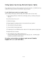
Страница 73: ...ng in the proper direction B Set Flow Control Valve on 6 C Start Tractor engine D Engage spinners by pushing remote lever forward into the lower position E This should start turning the spinners F Usi...

Страница 74: ......

Страница 75: ...Section 6 Flow Divider Assembly...

Страница 76: ......

Страница 77: ...5 4...

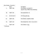
Страница 78: ...Flow Divider Assembly S S Specify Floor Width When Ordering B 300 FT 011 Flow Divider Bar S S C UCFL 204 10 5 8 Flange Bearing D 300 FT 012 Flow Divider Adjustment Rod E 300 FT 013 Flow Divider Hex N...

Страница 79: ...Section 7 Rigid Axle Assembly...

Страница 80: ...7 1 6 Bolt 7 000 per Pair Hub Assembly J I H G A F E C B D L K...

Страница 81: ...t Wheel Nut D 800 2 113 6 Bolt Hub Seal E 800 2 108 6 Bolt Inner Bearing F 800 2 109 6 Bolt Inner Race G 800 2 112 6 Bolt Outer Race H 800 2 111 6 Bolt Outer Bearing I 800 2 116 6 Bolt Spacer Washer J...

Страница 82: ...7 3 8 Bolt 12 000 per Pair Hub Assembly J I H G A F E C B D L K...

Страница 83: ...0 3 113 60 8 8 Bolt Wheel Nut D 800 3 108 60 8 Hub Seal E 800 3 104 60 8 Inner Bearing F 800 3 105 60 8 Inner Race G 800 3 107 60 8 Outer Race H 800 3 106 60 8 Outer Bearing I 800 3 112 60 8 Spacer Wa...

Страница 84: ...eel Part Tire and Wheel Part 6 14L x 16 1 8 16 1 x 11 C 32 800 1 102 800 1 110 800 1 120 Lug Nut Torque Specifications ft lbs Stud Size Part Number Torque ft lbs 9 16 800 2 118 110 125 Hub Bolt Patter...

Страница 85: ...Section 8 Basic Set Up Operation...

Страница 86: ...r desired rate of application 3 Adjust material divider accordingly 4 Engage Hydraulic Remote PTO control once engaged spinners should begin turning 5 Engage press wheel 6 Conduct a spread pattern pan...

Страница 87: ...e of hand tach reading 3 Adjust lever on flow control valve until desired speed is reached the higher the indicator number the faster the spinners should run 4 After getting correct spinner speed incr...

Страница 88: ...8 3...

Страница 89: ...T will cause the spread pattern to be heavy on the outside of the spread swath 3 Moving the Material Divider IN will cause the spread pattern to be heavy in the middle of the spread swath Material Div...

Страница 90: ......

Страница 91: ...Section 9 Maintenance Troubleshooting...

Страница 92: ...o check HYDRAULIC OIL level daily Located on the front of the oil tank is an oil temperature oil level gauge The oil level should be maintained within 1 inch of the black line at the top of the gauge...

Страница 93: ...ll times B Where excessive moisture exists it may be necessary to clean the material divider and spinners while in the field to achieve the best possible spread pattern C The material divider plays an...

Страница 94: ...Recommended Investigation A Basic Checks 1 Check to be sure indicator on flow control valve is located in its proper location Refer to spinner speed and spread pattern instructions 2 Check to be sure...

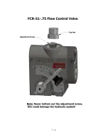
Страница 95: ...ating temperatures 2 Disengage PTO and install pressure gauge into CF port on flow control valve Refer to hydraulic flow control valve drawing page 3 7 3 Set lever on flow control valve on 10 4 Engage...

Страница 96: ...tight and properly in place D Check that the spinner discs are securely fastened Problem III Improper spread pattern Recommended Investigation A Check setting of material divider B Check spinner disc...

Страница 97: ...Section 10 Spread Pattern...

Страница 98: ...der while the machinery is in use or moving Wear eye protection and avoid discharge from spinners Do not ride on the spreader while in motion The spread pattern is affected by several factors includin...

Страница 99: ...etween 650 and 750 rpm for ordinary materials Once the initial testing is completed testing should be repeated at the beginning of each spreading season anytime maintenance or adjustments are made to...

Страница 100: ...e of less than 2 degrees Place a plastic grid into each of the 21 collection pans Position the 21 pans on 6 centers with the long side parallel to the direction of travel If possible perform test when...

Страница 101: ...10 4 Data Recording...

Страница 102: ...10 5 Data Recording Unacceptable Pattern Acceptable Pattern...

Страница 103: ...mount of material applied is half of the amount at the center of the pattern The distance between these two points represents the optimal swath width If spreading blended fertilizer a visual inspectio...

Страница 104: ...10 7 Acceptable Pattern Using a 3 Pass Switchback Driving Method...

Страница 105: ...ve the material divider towards the front of the spreader 2 Increase spinner speed 3 Check spinner blade condition Light Outside the Tractor s Tracks 1 Check spinner blade condition 2 Decrease spinner...

Страница 106: ...10 9 Notes...

Отзывы: