9 - 3
Cable Pinouts
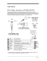
RS-232 Output, external power (IT4400 and IT4700)
Decoded output data format is provided at the modular connector in the
Imager.Interface cables normally supplied with the Imager are terminated with a
10 pin modular plug (P1) and a 9 pin Type D connector (P3) that is compatible
with all Welch Allyn decoders and terminals. See chart below.
P1
Pin 1
Pin 10
P3
9 Pin Type D Female
P3 connects to your terminal.
6
9
1
5
View A-A
P2
Power Pig Tail
P2 connects to
the external
power supply.
Inner
Outer
View B-B
10 Pin Modular Plug
P1 connects to the Imager.
Inner
Outer
P2
|
0
5
3
2
8
7
SH
Red
Black
Green
Blue
Brown
1
NC
No Connection
2
Ground
Supply Ground
3
+5VDC
Power Connection
4
Ground
Supply Ground
5
RXD
Receive Data - Serial Data to Imager
6
TXD
Transmit Data - Serial Data from Imager
7
+5VDC
Power Connection
8
RTS
Request to Send Data
9
CTS
Clear to Send Data
10
TRIG
External Trigger (IT4700 only)
1
SH
Drain Wire (Shield)
1. The HHLC mode is not available on an IT4700 with external trigger capability. Con-
tact the factory if you require HHLC capability for an IT4700.
Содержание IMAGETEAM 4400
Страница 4: ......
Страница 12: ...viii ...
Страница 16: ...1 4 IT4700 Imager Identification Enlarged View of Label Hand Held IT4700 Imager Bottom View ...
Страница 110: ...4 8 Exit Selections Save OCR Template Discard OCR Template ...
Страница 116: ...5 6 ...
Страница 146: ...6 30 ...
Страница 152: ...8 4 ...
Страница 158: ...9 6 ...
Страница 164: ...10 6 ...
Страница 168: ...11 4 ...
Страница 175: ......
Страница 178: ...Sample Symbols Aztec Aztec Mesa Code MaxiCode Micro PDF417 Package Label Test Message Test Message Test Message ...
Страница 179: ...Programming Chart 0 2 6 1 7 5 4 3 ...
Страница 180: ...Programming Chart 8 A E 9 F D C B Save Discard E ...
Страница 181: ...Programming Chart OCR a e d l Save Discard c t ...
Страница 182: ...4619 Jordan Road P O Box 187 Skaneateles Falls New York 13153 0187 44 4700 UG Rev H ...


