background image

[文件標題] 

[日期] 


23 

Vol. 1.2 © 2020 Hanbell Precise Machinery Co., Ltd. 

All rights reserved 


4.3 Motor Temperature Control 

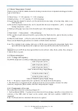
There are six set of Pt100 installed in motor winding to monitor motor temperature and suggest control 
logic is listed below: 
1. 

Motor Temp.

T

90

(alarm)

T > 100

(tripping) 

Bearing Temp.

T

75

(alarm)

T > 85

(tripping)   

Liquid  injection  should  be  turned  on  if  the  alarm  from  motor  temp.  or  bearing  temp.  alarm  is  on 

(refer figure4.4) 

The auxiliary liquid solenoid valve can be closed when the motor temperature 

80

  or magnetic 

bearing temperature 

≦65℃. 

Bearing cooling (gas type) stop valve should be open when compressor running. 

2. 

Shaft stretch

>300µ m(alarm)

>400µm(tripping) 

The  auxiliary  liquid  solenoid  should  be  opened  when  the  Shaft  stretch  is  greater  than  the  warning 

value. 

When the shaft stretch 

250

μ

m can be turn off auxiliary liquid solenoid. 

Please consult Hanbell representatives for details on Shaft stretch calculation. 
 
Note:  The  controller  must  warning  when  one  of  Pt100  sensor  detecting  the  temperature  higher  than 

upon definition temperature, and compressor must stop until the reason has been found out. 


Remark

Six sets of Pt100 are showing in different color with red, white, black, yellow, blue, and gray. 

Common line is in green. 
 

4.4 Motor connection 
4.4.1


Voltage & Frequency 

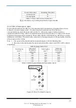
The RTM compressor is working on following power supply range: 

380V±5%(342V~418V) 

400V±5%(360V~440V) 

460V±5%(414V~506V) 

Table 4.1 Rated Voltage Supply Range 


50 Hz±3%(47Hz~53Hz) 

60 Hz±3%(57Hz~63Hz) 

Table 4.2 Rated Frequency Supply Range 

Note

1. Frequency is applied for power generator, not compressor motor frequency.         

2. The chart above is suggested for the compressor and its accessory such as inverter. For other 
electronic components, please double check their designed power supply. 
 

4.4.2 Components of inverter 

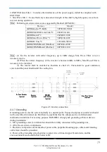
The connection of inverter is showing in figure 4.5


1. No-Fuse Breaker(NFB)

To protect an electrical circuit from damage caused by excess current, the 

selection  of  the  NFB  shall  be  based  on  the  current  under  full  load  condition.  600DCV/16A  is 
suggested 
Note

Full load current is calculated when reactor is applied. 

Содержание RTM-090

Страница 1: ... 文件標題 日期 1 Vol 1 2 2020 Hanbell Precise Machinery Co Ltd All rights reserved Magnetic Centrifugal Compressor RTM 090 ...

Страница 2: ...ve 11 3 Suction Structure 12 3 1 Inlet Guide Vanes 12 3 1 1 Control of inlet guide vanes 12 3 2 Vane actuator control 13 3 2 1 Actuator data 13 3 2 2 Electrical connections 14 3 2 3 Wiring 14 3 2 4 Control info 15 3 2 5 Troubleshooting 17 3 3 Capacity adjustment 18 3 4 Equation of safety margin line 18 3 5 Hot gas bypass HGBP 19 3 6 Middle pressure stop valve 20 4 1 Motor cooling 21 4 1 1 Heater 2...

Страница 3: ... 30 5 5 MBC connection data 31 5 5 1 Additional info about connection port 31 5 5 2 Communication of MBC and PLC 31 5 6 Total Harmonic Distortion THD info 31 5 7 THD installation fix 32 5 8 THD connector 33 5 9 Variable Frequency Drive VFD Connector 34 5 10 Parameter of inverter 34 6 Compressor lifting and installation 35 6 1 Compressor lifting 35 6 2 Compressor installation 35 7 Instructions 37 7...

Страница 4: ... Shaft made of high strength alloy Impellers closed type made of high strength aluminum Bearings magnetic bearings Motor permanent magnet synchronous motor independent cooling by liquid refrigerant Enclosure IP54 protection Ambience RTM series compressors should be stored and operated within the following ambient temperature Storage 25 55 Operation Water cooled ET 2 14 CT 15 55 Note 1 Please refer...

Страница 5: ... 45 50 55 60 0 2 4 6 8 10 12 14 16 18 20 22 Saturated Condensation Temperature Saturated EvaporationTemperature Pr 3 0 Pr 2 5 Pr 2 0 Pr 1 5 Figure 2 1 RTM 090 application limits Note Please refer to the latest compressor selection software for specific compressor capacity Note This range represents the range of FLA at 380V and the limits for maximum condensation temperature SCT and evaporation tem...

Страница 6: ...ole Permanent magnet Starting VFD Voltage V 380 460 5 Insulation Class H Protection PT100 6 Transmission Type Direct driven Lubrication Oil free Dimension LxWxH m 1 3 X 0 8 x 0 7 Weight kg 1050 Hydrostatic pressure test kg cm g 22 Refrigerant heater kW 1x 0 3 Table 2 1 Compressor specifications RTM 090 Performance USRT RPM COP IPLV 400 13 000 6 53 11 0 450 13 500 6 33 10 5 Table 2 2 Compressor per...

Страница 7: ... 文件標題 日期 7 Vol 1 2 2020 Hanbell Precise Machinery Co Ltd All rights reserved 2 4 Compressor outline ...

Страница 8: ...ote 1 Please weld steel pipes onto flanges by butt welding and make sure debris has been cleaned otherwise the compressor might be damaged during running Flow velocity in the discharge side of the compressor could be as high as 15 20 m sec High speed discharge gas will make noise in discharge connection In order to decrease the noise level it s recommended to round sharp edges of joints of piping ...

Страница 9: ...ll rights reserved Figure 2 4 Discharge and suction piping Note Residue from welding might damage the compressor seriously 1防熱橡膠 2鉛板層 2 3mm 3隔音棉 4表層膠帶 Figure 2 5 Enclosure of piping connection 1Heatproof rubber 2Laminated lead 2 3mm 3Acoustic foam 4Gummed tape ...

Страница 10: ...1 32 64 20 3 80mm 133 48 73 104 168 111 16 11 32 64 20 4 100mm 171 52 94 120 191 111 16 11 32 64 19 5 125mm 191 57 122 129 191 130 19 13 32 114 24 6 150mm 219 57 149 141 203 130 19 13 32 114 24 8 200mm 273 61 198 176 241 130 22 16 32 114 24 10 250mm 332 70 248 217 273 155 30 22 51 114 27 Remark Dimension C is minima size when the valve opened totally unit mm Operation Temp 29 260 Operation Pressur...

Страница 11: ... mm B mm C mm E mm 6 150mm 222 2 120 7 95 3 70 8 200mm 279 4 163 5 116 7 74 6 Remark Operating temp 260 810 Hydraulic pressure testing 31 6kg cm2 API 598 Material ASTAM351 GR CF8M stainless steel Pressure level ASME 150 The check valve is of wafer plate valve Use ANSI 150 standard flange Table 2 4 Check valve size No Name Material 1 Valve CF8M 2 Disc shield A351 CF8M 3 Spring SUS316 4 Alignment pi...

Страница 12: ...inlet guide vanes are automatically controlled through a vane actuator with a lever arm and IGV opening ranges from 20 minimum load to totally open Opening of the vane actuator in percentage has a linear relation to the control signal voltage However cooling capacity does not relate the angle changes of guide vanes Therefore vane actuator s opening in percentage is not the same as the cooling capa...

Страница 13: ...ec 60Hz TRAVEL ANGLE 0 90 RATED OPERATION TIME Continuous 100 RESOLUTION Over 1 250 DEAD ZONE Max 0 5 PROTECTION Motor thermal protector 120ºC AMBIENT TEMPERATURE Ambient temperature within 25 55ºC RATED CURRENT 0 4A 220V 0 7A 110V MOTOR 20W INSULATION GRADE Class E INSULATION RESISTANCE Between power terminal case 500V DC 100MΩ WITHSTAND VOLTAGE Between power terminal case 1500V AC 1 minute WIRE ...

Страница 14: ... 1 5A fuse or breaker should be installed in main power supply Voltage stabilizer is required to avoid the damage caused by the imbalance of voltage within 10 2 Signal wires for control should be shielded to prevent them from interference 3 The actuator wiring shall not be parallel to the power cables 3 2 3 Wiring Make effective water proof if vinyl tubes or conduits are used Figure 3 3 Wiring Cab...

Страница 15: ...l Precise Machinery Co Ltd All rights reserved 3 2 4 Control info Figure 3 4 Control pack Figure 3 5 Switcher Select switch for off mode Select switch for action mode External terminal block SPAN volume Zero volume Sensitivity volume ...

Страница 16: ...nal interruption Note When the input signal is less than 2mA the actuator is judged to be interrupted and transferred to the specified state so the control device and signal 4 20mA must be adjusted correctly Select switch for action mode Select switch for off mode 1 Direct action Input signal 20mA Close Input signal 4mA Open 3 Reverse action Input signal 4mA Open Input signal 20mA Close Select swi...

Страница 17: ...qualified personnel 3 2 5 Troubleshooting TROUBLE PROBABLE CAUSE SOLUTION Motor does not start up 1 Power failed or dropped 2 Signal failed or dropped 3 Wire broken or disconnected 4 Thermal protector functioned 5 Limit switches functioned at an intermediate position 6 Motor advancer defective 7 Control pack defective 1 Check and supply power 2 Check and input signals 3 Change the wire or re conne...

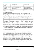
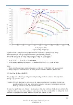
Страница 18: ...s to surge line the unloading will be controlled by IGV 3 The control for target water temp is based on input signal and output signal is used for setting the frequency and opening of IGV It is suggested to install anti interference devices on chiller unit 3 4 Equation of safety margin line Description of Surge When the centrifugal compressor is at part load the angle of guide vane becomes smaller...

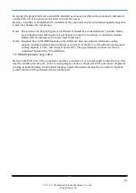
Страница 19: ...erant or liquid refrigerant from condenser into evaporator through a proportional valve Function When the load reaches certain value the surge would happen To continue the low load operation the hot gas by pass valve can be opened to increase suction pressure and lower discharge pressure as well as compression ratio Because hot gas bypass is to transfer compressed gas from the condenser high press...

Страница 20: ...maintain constant chilled water temperatures from zero load to full load Note2 Required flow for HGBP depends on the difference between required minimum cooling capacity and the minimum load compressor can reach If the IGV is at minimum opening and cooling capacity is 50 and end user needs 20 The pipe diameter and flow need to be considered based on the 30 difference 3 6 Middle pressure stop valve...

Страница 21: ...nt be fluid Figure 4 1 Motor Bearing Cooling 4 1 1 Heater One 300W UL approved heater has been installed in every compressor as a standard accessory The function of the heater is to prevent condensation of refrigerant inside compressor Before restart of compressor after shutdown for a long time please turn on heater at least 24 hours Figure 4 2 Heater Spec 300W 110V or 220V IP 54 UL certified Note...

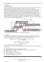
Страница 22: ...ed wire Figure 4 3 Pt100 thermostat 4 2 Liquid returned from motor and bearings The piping connection is showing in Figure 4 4 Motor Cooling Outlet is connected to Economizer Bearing Cooling Outlet is connected to Evaporator Note Bearing Cooling Outlet is connected to Evaporator to reduce the pressure inside motor chamber Figure 4 4 Cooling system ...

Страница 23: ...warning when one of Pt100 sensor detecting the temperature higher than upon definition temperature and compressor must stop until the reason has been found out Remark Six sets of Pt100 are showing in different color with red white black yellow blue and gray Common line is in green 4 4 Motor connection 4 4 1 Voltage Frequency The RTM compressor is working on following power supply range 380V 5 342V...

Страница 24: ...he cooling fan No Fuse Breaker No Fuse Breaker No Fuse Breaker No Fuse Breaker option option option option EMC EMI EMC EMI EMC EMI EMC EMI Line Filter Line Filter Line Filter Line Filter option option option option Reactor Reactor Reactor Reactor option option option option Inverter Inverter Inverter Inverter option option option option Sine Wave Filter Sine Wave Filter Sine Wave Filter Sine Wave ...

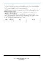
Страница 25: ... cable wire terminals and equipment are necessary to comply with various regulations and engineering requirement Power cables shall be with braid sleeve and able to avoid the interference with others The power cable connection is showing on figure 4 6 Please double check the phase sequence when wiring Note 1 The power cable gland should be insulated properly with heat shrinking tube 2 The power ca...

Страница 26: ...nsion ease devices to support the high voltage cables must be applied HANBELL does not provide wiring terminals 4 When tightening the terminals of power bolts use torque wrench with the torque lower than 700kgf cm 5 8 9 16 copper nut 5 Cable wiring and construction inspection rules must follow local electrical regulations 6 The insulation material of the main power and control cables should be scr...

Страница 27: ... 文件標題 日期 27 Vol 1 2 2020 Hanbell Precise Machinery Co Ltd All rights reserved 5 Control line connection MBC THD typical I O connections ...

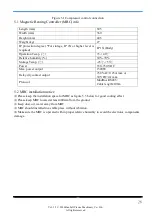
Страница 28: ... 30 70 Storage Temp 25 55 Power 350 750 VDC Max power output 1500W Relay dry contact output 250 VAC 0 25A max or 30 VDC 2A max Protocol ModBus RS485 Cable length 100m 5 2 MBC installation notice Please keep the installation space for MBC as figure 5 3 below for good cooling effect Please keep MBC located at least 400mm from the ground Keep dust oil water away from MBC MBC should installed in a sta...

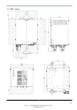
Страница 29: ... 文件標題 日期 29 Vol 1 2 2020 Hanbell Precise Machinery Co Ltd All rights reserved 5 3 MBC outline Fan airflow Fan airflow ...

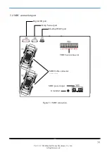
Страница 30: ...MBC connection port Figure 5 1 MBC connection Digital I O port Temp Sensor port Modbus RS485 port MBC Cable connector connector THD board connector MBC power input Grounded 123456 1 2 3 4 5 6 7 8 9 10 11 1 2 3 4 5 6 7 8 9 10 11 1 2 3 4 5 6 7 8 9 10 11 1 2 3 4 5 6 7 8 9 10 11 12345678 ...

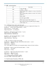
Страница 31: ...y open 0V Levitation OFF Reply closed 24V Levitation ON Digital In 2 Rotation X4 terminal number 3 and 4 Reply open 0V Rotation OFF Reply closed 24V Rotation ON Digital In 3 Reset X4 terminal number 5 and 6 Reply open 0V Reset OFF Reply closed 24V Reset ON 2 XB3 The signal from relay inside of MBC Digital Out1 Shut Down Request SDR XB3 terminal number 1 and 2 Reply open SDR ON Reply closed SDR OFF...

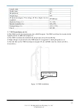
Страница 32: ...VDC 5 7 THD installation fix The THD board is provided mounted on a RS100 support The THD board must be mounted in the upright position on DIN rail as figure 5 2 The THD board must be installed with proper space away from cable tray High voltages are presented on the THD board It is suggested to install plexiglass cover The link between the THD board power supply 24Vdc and MBC must be carried out ...

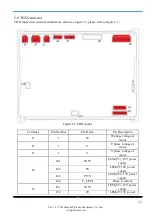
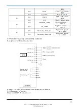
Страница 33: ...to figure 5 1 Figure 5 3 THD outline Terminal Pin Number Pin Name Pin Description J1 1 W W phase voltage of motor J2 1 U U phase voltage of motor J3 1 V V phase voltage of motor J4 J4 1 N15V LEM CT 15V power supply J4 2 0V LEM CT 0V power supply J4 3 P15V LEM CT 15V power supply J4 4 U_LEM Phase U current J5 J5 1 N15V LEM CT 15V power supply J5 2 0V LEM CT 0V power ...

Страница 34: ...tput isolated J7 5 0V_AMB Top Tour output isolated J9 J9 1 Harmonic_Alarm_1A Dry contact open in case of alarm J9 2 Harmonic_Alarm_1B Dry contact open in case of alarm 5 9 Variable Frequency Drive VFD Connector Description of KEB inverter connection Remark The figure is only for KEB other brands may be different 5 10 Parameter of inverter Please refer KEB VFD parameter 1 1 X2A Error output of pass...

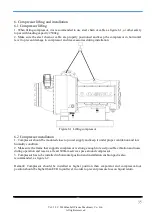
Страница 35: ...e 6 1 Lifting compressor 6 2 Compressor installation 1 Compressor should be mounted close to power supply and keep it under proper ventilation and low humidity condition 2 Make sure the frame that supports compressor is strong enough to resist possible vibration and noise during operation and reserve at least 600mm service space around compressor 3 Compressor has to be installed in horizontal posi...

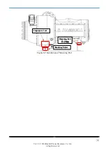
Страница 36: ...rights reserved Figure 6 2 Installation of Mounting Pad Compressor foot Compressor foot Compressor foot Compressor foot Mounting Screw Mounting Screw Mounting Screw Mounting Screw Mounting Pad Mounting Pad Mounting Pad Mounting Pad 15 20mm 15 20mm 15 20mm 15 20mm ...

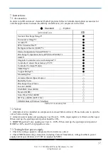
Страница 37: ... Actuator Heater Special spec Butterfly Valve Discharge Check Valve Inverter KEB EMI EMC filter KEB Reactor KEB Sine Wave Filter KEB DC Fuse KEB 600V 16A COMM Board Profinet Modbus Table 8 1 Accessory list 7 2 Valves 1 All kinds of valves installed on compressor are closed before delivery Please make sure to open the valves before testing run 2 Actuator power supply and opening test test from 0 10...

Страница 38: ...heck valve should be installed in discharge pipe and the pressure drop should be as small as possible The pressure and temperature is high in discharge side so the material and quality of check valve has to be reliable 3 If compressor is operated under humid circumstance proper preservation and protection is necessary 4 If compressor is shut down for a long term especially in the winter refrigeran...

Страница 39: ...Condensing Temperature EMC Electromagnetic Compatibility EMI Electromagnetic Interference ET Evaporator Temperature GB National Standards of People s Republic of China HGBP Hot Gas By Pass IGV Inlet Guide Vane IP Industry Pack JIS Japanese Industrial Standards LEM Current Transformer CT MBC Magnetic Bearing Control RTM Hanbell Oil free centrifugal UL Underwriters Laboratories Inc VDC Direct Curren...

Отзывы: