


HAMWORTHY HEATING LTD. PUREWELL AUTOMATIC IGNITION 500001035/G
11
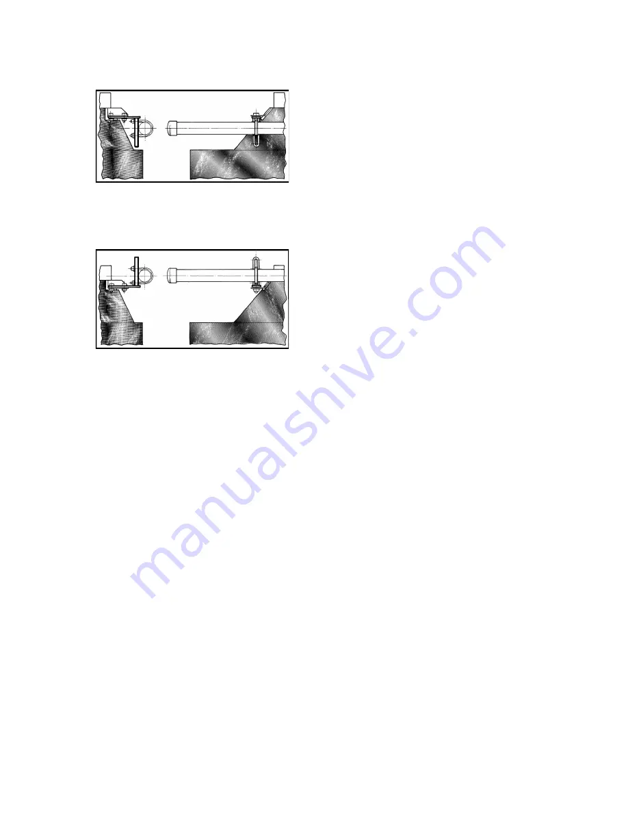
Figure No. 6b shows the pipe clamp fitted to Purewell
60, 70, 80 and 120 kW boilers.
Figure No. 6b
Figure No. 6c shows the pipe clamp fitted to Purewell
40, 50, 95 and 105 kW boilers.
Figure No. 6c
Tighten screws ensuring ‘U’ clamp threads do not
damage insulation. It may be necessary to remove
the bottom thread of the ‘U’ clamp with the bracket in
lower position as it may foul the draught hood. Ensure
no undue stress is placed on the gas pipe/manifold
and ensure pipe is vertical/horizontal before clamping
in position.
10.4 Connection of Boilers to the Flue System
.
Notes on the recommendation for design of the flue
system are given in
Section 6:FLUE SYSTEM.
10.4.1 Standard Diverter models: -
When supplied with a draught diverter, it must be
fitted to the boiler as supplied,
NO
modifications are
permitted on site. Prior to fitting the assembly to the
boiler, the top casing panel should be removed from
its packing and placed in position. Fitting this panel
after the flue is fitted is not recommended. Care
should be taken to ensure the seal between primary
flue pipe and boiler spigot is sound as a leak may
affect the boilers’ operation.
10.4.2 Low Line models: -
The Low Line model incorporates its own draught
diverter and care must taken to ensure the seal
between the outlet spigot and flue pipe is sound to
avoid the escape of flue gas.
10.2.3
The top panel will require protecting to ensure
no damage occurs to the plastic coating during
subsequent site assembly of other components. It is
important, for service requirements, that the flue
system is fully self-supporting. Check the flue and
chimney are clear from obstruction.
10.5
Gas Connection
The Purewell boiler is supplied with a gas pipe which
when assembled exits the casing at the rear, see
Figure No. 9 for position. The incoming mains gas
supply must be capable of supplying gas to the boiler
at the required pressure, under all firing conditions.
For sizing information see Figure No. 11. An approved
isolating valve & union should be installed for each
boiler in a convenient and safe position and be clearly
marked.
10.6
Water Connections
See Figure No. 9 for position of water connections
(flow and return). A
1
/
2
” BSP plug is fitted local to the
return connection for the fitting of a drain cock, NOTE!
(Not HHL supply). Care must be taken when installing
water system pipework that undue stress is avoided
on the boiler flow and return connections. It is
recommended that unions are fitted local to the boiler
to permit future servicing requirements.
Fully closing valves must not be connected to both
flow and return pipes unless the boiler is fitted with an
individual, correctly sized safety valve. It is
recommended that a 3-way ‘L’ port valve is fitted in
the flow connection to allow an open vent situation
should the boiler need to be fully isolated from the
system.
10.7 Casing and Controls Assembly
For assembly of casing components and controls unit
see Figure No. 7.
Содержание Purewell
Страница 4: ...HAMWORTHY HEATING LTD PUREWELL AUTOMATIC IGNITION 500001035 G ii THIS PAGE LEFT INTENTIONALLY BLANK ...
Страница 19: ...HAMWORTHY HEATING LTD PUREWELL AUTOMATIC IGNITION 500001035 G 13 Figure No 7a Exploded View of Casing Set ...
Страница 28: ...HAMWORTHY HEATING LTD PUREWELL AUTOMATIC IGNITION 500001035 G 22 Figure No 10 General Layout Front View ...
Страница 40: ...HAMWORTHY HEATING LTD PUREWELL AUTOMATIC IGNITION 500001035 G 34 THIS PAGE LEFT INTENTIONALLY BLANK ...