


HAMWORTHY HEATING LTD. PUREWELL AUTOMATIC IGNITION 500001035/G
6
6.6 Flue Discharge
The flue system must ensure safe and efficient
operation of the boiler to which it is attached, protect
the combustion process from wind effects and
disperse the products of combustion to the external
air.
The flue must terminate in a freely exposed position
and be so situated as to prevent the products of
combustion entering any opening in a building.
Where the flue diameter is less than 200mm (8") a
terminal must be fitted. Where the flue is of a larger
size consideration should be given to the fitting of a
flue discharge terminal or grill to stop ingress of birds,
etc.
6.7
Surface Temperatures
Combustible materials in the vicinity of the boiler and
flue shall not exceed 65
°
C during boiler operation.
The flue shall not be closer than 50mm to any
combustible material, except where it passes through
such material with a non-combustible sleeve when
the air gap may not be less than 25mm.
6.8 Flue System Location
The flue system must not be placed or fitted where
there is undue risk of accidental damage to the flue
pipe or undue danger to persons in the vicinity.
NOTE!
The flue
MUST
be self-supporting. Check
that the flue and chimney are clear from any
obstruction.
7.0
AIR SUPPLY
Detailed recommendations for air supply are given in
BS 6644
. The following notes are intended to give
general guidance. In all cases there must be provision
for an adequate supply of air for both combustion and
general ventilation, in addition to that required for any
other appliance.
7.1
Air Supply by Natural Ventilation
The boiler room must have, or be provided with,
permanent air vents directly to the outside air, at
high level and at low level. For an exposed boiler
house, air vents should be fitted preferably on all
four sides, but at least on two sides. Air vents
should have negligible resistance and must not be
sited in any position where they are likely to be
easily blocked or flooded or in any position adjacent
to an extraction system which is carrying flammable
vapour. Grilles or louvres must be so designed that
high velocity air streams do not occur within the
space housing the boiler.
The air supplied for boiler house ventilation shall be
such that the maximum temperatures within the boiler
house shall be as follows:
1) At floor level (or 100mm above) = 25
°
C.
2) At mid-level (1.5m above floor level) = 32
°
C.
3) At ceiling level (or 100mm below) = 40
°
C.
Where both low and high level openings are used,
the grilles shall have a total minimum free area of: -
Low Level (inlet): 540cm
2
plus 4.5cm
2
per Kilowatt in
excess of 60kW total rated input.
High Level (outlet): 270cm
2
plus 2.25cm
2
per Kilowatt
in excess of 60kW total rated input.
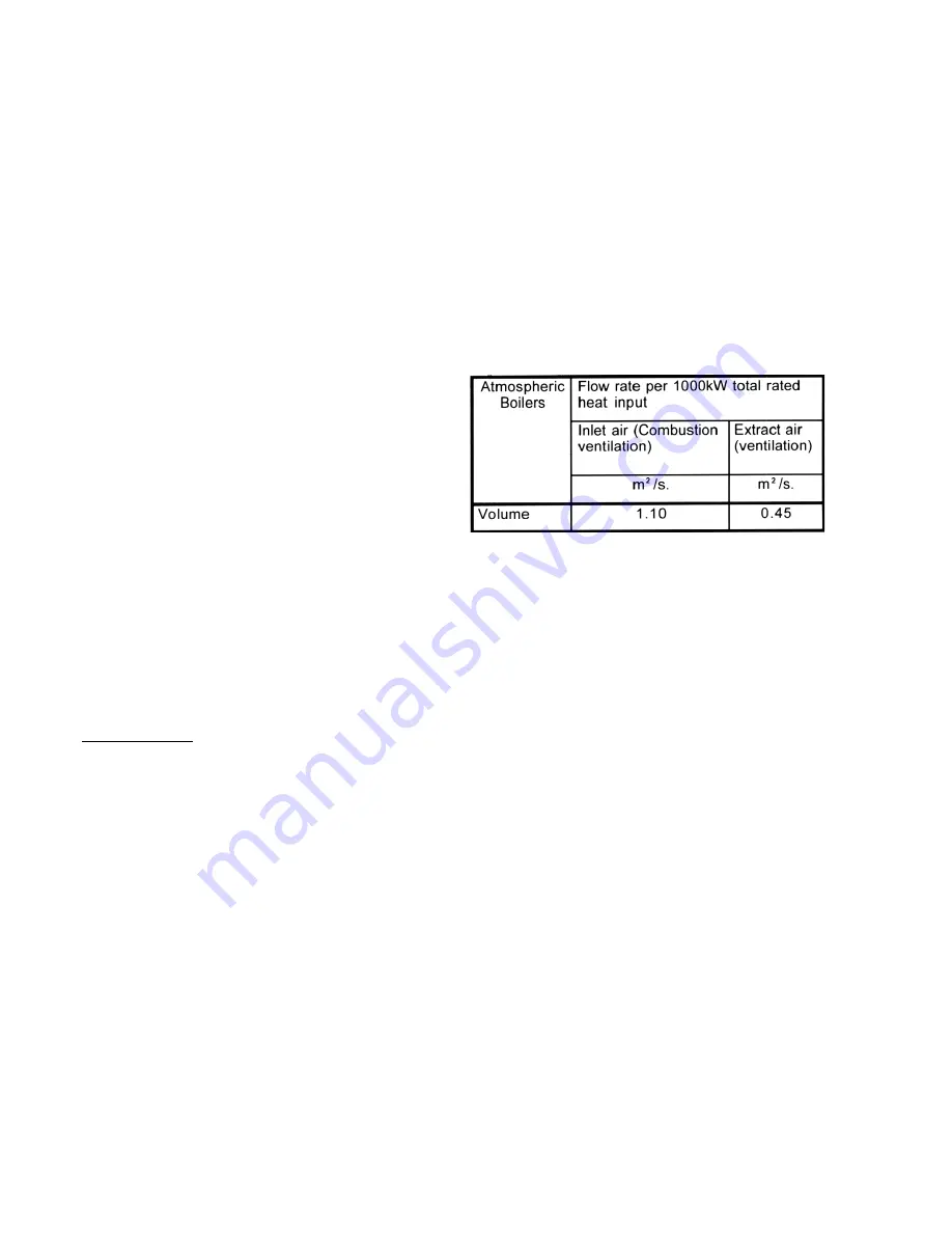
Figure No 4 - Mechanical Ventilation Flow Rates
7.2
Air Supply by Mechanical Ventilation
Air supplied to the boiler room by Mechanical means
should be as follows: -
1) Mechanical inlet and mechanical extract can be
utilised providing design extraction rate does not
exceed one third of the design inlet rate.
2) Mechanical extract ventilation with natural inlet
ventilation
MUST NOT
be used.
NOTE:
For Mechanical ventilation systems an
automatic control should be provided to cut off the
gas supply to the boiler, in the event of failure of air
flow in either inlet or extract fans.
Содержание Purewell
Страница 4: ...HAMWORTHY HEATING LTD PUREWELL AUTOMATIC IGNITION 500001035 G ii THIS PAGE LEFT INTENTIONALLY BLANK ...
Страница 19: ...HAMWORTHY HEATING LTD PUREWELL AUTOMATIC IGNITION 500001035 G 13 Figure No 7a Exploded View of Casing Set ...
Страница 28: ...HAMWORTHY HEATING LTD PUREWELL AUTOMATIC IGNITION 500001035 G 22 Figure No 10 General Layout Front View ...
Страница 40: ...HAMWORTHY HEATING LTD PUREWELL AUTOMATIC IGNITION 500001035 G 34 THIS PAGE LEFT INTENTIONALLY BLANK ...