background image

14

Assembly — Installing the Light Kit 

Attaching the switch housing to
the mounting ring

12

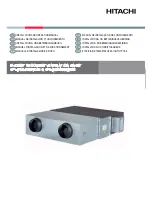
Attaching the light kit assembly to
the switch housing

13

Remove one of the three switch housing mounting screws 
(PP) from the mounting ring (QQ) and loosen the other two 
screws (PP). (Do not remove.)

While holding the switch housing (I) under the fan motor 
assembly (F), snap together the wire connection plugs (RR).

Place the key holes in the switch housing (I) over the two 
screws (PP) previously loosened from the mounting ring 
(QQ). Turn the switch housing (I) until the switch housing (I) 
locks in place at the narrow section of the key holes.

Securely tighten the two switch housing mounting screws 
(QQ) previously loosened and the one (QQ) previously 
removed.

CAUTION:

 Before starting installation, disconnect the 

power by turning off the circuit breaker or removing the fuse 
at the fuse box. Turning power off using the fan switch is not 
sufficient to prevent electric shock.

Remove one of the three light kit mounting screws (SS) from 
the switch housing (I) and loosen the other two screws (SS). 
(Do not remove.)

While holding the light kit assembly (J) under the fan motor 
assembly (F), snap together the two wire plugs (TT):
- White to white
- Blue to black

Place the key holes in the light kit assembly (J) over the two 
screws (SS) previously loosened from the switch housing (I). 
Turn the light kit assembly (J) until the light kit assembly (J) 
locks in place at the narrow section of the key holes. Secure 
by tightening the two light kit mounting screws (SS) previously 
loosened and the one (SS) previously removed.

I

F

QQ

PP

RR

J

TT

F

SS

I

Содержание SEAPORT II YG991-MBK

Страница 1: ...osing Hampton Bay 1 855 HD HAMPTON HAMPTONBAY COM Questions problems missing parts Before returning to the store 8 a m 7 p m EST Monday Friday 9 a m 6 p m EST Saturday call Hampton Bay Customer Servic...

Страница 2: ...ctor on one side of the outlet box and ungrounded conductor on the other side of the outlet box All set screws must be checked and retightened where necessary before installation 1 2 3 4 5 6 7 8 9 WAR...

Страница 3: ...your responsibility Damage to any part such as by accident misuse improper installation or by af xing any accessories is not covered by this warranty Because of varying climatic conditions this warran...

Страница 4: ...OTE Hardware not shown to actual size AA BB CC DD Plastic wire nut 9 watt LED bulb Pull chain and fob Hex wrench Part Description 3 2 2 1 Quantity HARDWARE INCLUDED Pre Installation continued DD CC BB...

Страница 5: ...Light cover assembly Quantity 5 5 1 1 1 Part A B C D E F Quantity 1 1 1 1 1 1 Description Mounting bracket preassembled Canopy Canopy bottom cover preassembled Hanger ball downrod assembly Coupling co...

Страница 6: ...on hanger bar not included as shown above Outlet Box Outlet Box Hanger Bar Outlet Box Recessed Outlet Box A WARNING To reduce the risk of re electric shock or personal injury mount the fan to an outle...

Страница 7: ...downrod is needed not included take out the screw located in the hanger ball lower the hanger ball and remove the pin Remove all three pieces from the downrod and assemble them onto the new longer dow...

Страница 8: ...provided with the outlet box Note that the at side of the mounting bracket A is toward the outlet box Securely tighten the two mounting screws WARNING The tab in the ring must rest in the groove of th...

Страница 9: ...your fan installed by a licensed electrician Follow the steps below to connect the fan to your household wiring Use the plastic wire nuts AA with your fan Secure the plastic wire nuts AA with electri...

Страница 10: ...dual switch the fan and light can be turned on or off separately Make wire connections as follows using the wire nuts AA Wall switch not included From Fan To Outlet Box Black Wire for Fan Black Wire H...

Страница 11: ...ise until it locks in place at the narrow section of the key holes Align the circular hole on the canopy B with the remaining hole on the mounting bracket A secure the canopy mounting screw EE previou...

Страница 12: ...to the blade arm Press down the spring locking mechanism JJ to release the blade G from the blade arm H Slide the blade G toward the blade arm H until the blade G disengages from the spring locking m...

Страница 13: ...n the blade arms H Tighten the two blade arm screws with lock washers OO already installed in the blade arms H Repeat this procedure for the remaining blade assemblies F MM H G NN OO 13 11 Fastening t...

Страница 14: ...sened and the one QQ previously removed CAUTION Before starting installation disconnect the power by turning off the circuit breaker or removing the fuse at the fuse box Turning power off using the fa...

Страница 15: ...o remove four light cover assembly mounting screws UU from the light kit J Secure the light cover assembly K to the light kit J tightly with four light cover assembly mounting screws UU by using the h...

Страница 16: ...r depend on factors such as the room size ceiling height and numbers of fans The light pull chain controls the light kit ON and OFF Operation PULL CHAIN OPERATING INSTRUCTIONS REVERSE SWITCH OPERATING...

Страница 17: ...against each other or the interior wall of the switch housing Allow a 24 hour breaking in period Most noises associated with a new fan disappear during this time If using the ceiling light kit make s...

Страница 18: ...pursuant to Part 15 of the FCC Rules These limits are designed to provide reasonable protection against harmful interference in a residential installation This equipment generates uses and can radiate...

Отзывы: