background image

FPI FIREPLACE PRODUCTS INTERNATIONAL LTD.  6988 Venture St., Delta, BC  Canada, V4G 1H4

WARNING:
If the information in these instructions are not followed exactly,
a fire or explosion may result causing property damage,
personal injury or loss of life.

FOR YOUR SAFETY
Do not store or use gasoline or other flammable vapors and
liquids in the vicinity of this or any other appliance.

Installation and service must be performed by a qualified
installer, service agency or the gas supplier.

FOR YOUR SAFETY
What to do if you smell gas:

Do not try to light any appliance
Do not touch any electrical switch:
do not use any phone in your
building.
Immediately call your gas supplier
from a neighbour's phone. Follow
the gas supplier's instructions.
If you cannot reach your gas sup-
plier, call the fire department.

918-085b

MODELS:      H35-NG Natural Gas       H35-LP Propane

01/09/06

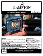
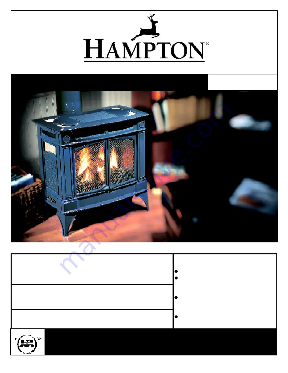
H35 Direct Vent Gas Fireplace

Owners &

Installation Manual

www.hampton-fire.com

Tested by:

Installer

: Please complete the details on the back cover

and leave this manual with the homeowner.

Homeowner:

 Please keep these instructions for future reference.

Содержание Hampton H35-NG

Страница 1: ...ncy or the gas supplier FOR YOUR SAFETY What to do if you smell gas Do not try to light any appliance Do not touch any electrical switch do not use any phone in your building Immediately call your gas supplier from a neighbour s phone Follow the gas supplier s instructions If you cannot reach your gas sup plier call the fire department 918 085b MODELS H35 NG Natural Gas H35 LP Propane 01 09 06 H35...

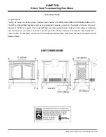
Страница 2: ...hand crafted appliance and has been designed to provide you with all the warmth and charm of a wood fireplace at the flick of a switch The model H35 has been approved by Warnock Hersey for both safety and efficiency As it also bears our own mark it promises to provide you with economy comfort and security for many trouble free years to follow Please take a moment now to acquaint yourself with thes...

Страница 3: ... Manufactured Home After First Sale 5 Before You Start 5 General Safety Information 6 Installation Checklist 6 Clearances to Combustibles 6 Locating Your Gas Stove 7 Manufactured Mobile Home Requirements 7 Combustion and Ventilation Air 7 Optional Fan Installation 7 Venting Introduction 8 Installation Precautions 8 Safety Precautions for the Installer 8 Vent Restrictor Position 8 Exterior Vent Ter...

Страница 4: ...Check the label on the unit and if there is a difference the label on the unit is the correct one Copy of Safety Label for H35 NG H35 LP For the State of Massachusetts installation and repair must be done by a plumber or gasfitter licensed in the Commonwealth of Massachusetts For the State of Massachusetts flexible connectors shall not exceed 36 inches in length FortheStateofMassachusetts theappli...

Страница 5: ...edicated 8 ground lug to which an 18 gauge copper wire from the steel chassis ground must be attached Thisappliancemayonlybeinstalledin an aftermarket permanently located manufactured USA only or mobile home where not prohibited by local codes This appliance is only for use with the type of gas indicated on the rating plate This appliance is not converti ble for use with other gases unless a certi...

Страница 6: ...Clearances to Combustibles page 6 location of unit page 7 and venting requirements pages 8 15 2 Install Optional Fan see page 7 3 Set vent restrictors page 8 4 Install venting Check all venting require ments pages 8 15 Vertical Termination with Co linear Flex System page 16 Hor izontal Termination Kits page 17 Dura Vent Termination Kits page 19 5 Make gas connections page 24 Test the pilot Must be...

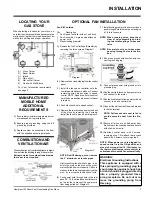
Страница 7: ...inum air intake pipes Hint for pushing fan down onto pins rub a bit of dish soap on the pins so the grom mets will slide down more easily Check to makesurethefanisseatedproperlyonthe pins try to move the fan back and forth 6 Push power cord through hole in the rear panel14 16 andtiealooseknotinthecord on the inside to prevent the power cord from being pulled out Diagram 2 7 Install locking grommet...

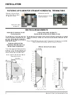
Страница 8: ...n walls and ceilings VENTING INTRODUCTION TheHorizontalTerminationKitandtheSimpson Dura Vent Direct Vent System Model DV GS venting systems in combination with the Direct Vent Freestanding Gas Stoves H35 NG and H35 LP have been tested and listed as direct vent heater systems by Warnock Hersey Theseunitsusethe balanced flue technology Co Axialsystem Theinnerlinerventsproducts of combustion to the o...

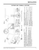
Страница 9: ...p min 12 30cm with Riser Vent min 6 15cm H Not to be installed above a meter regulator assembly within 3 90cm horizontally from the centerline of the regulator J Clearance to service regulator vent outlet min 36 90cm K Clearance to non mechanical air supply inlet to building or the combustion air inlet to any other appliance 12 30cm L Clearance to a mechanical air supply inlet min 72 1 8m M Cleara...

Страница 10: ...th 7 Black N A N A 4D7AB Adjustable Length 12 Galvinized N A N A 4D12A Adjustable Length 12 Black N A N A 4D12AB 45O Elbow Galvinized 945 4DT EL45 4D45L 45O Elbow Black 945B 4DT EL45B 4D45LB 45O Elbow Swivel Galvinized 945G N A N A 45O Elbow Swivel Black 945BG N A N A 90O Elbow Galvinized 990 4DT EL90S 4D90LS 90O Elbow Black 990B 4DT EL90SB 4D90LBS 90O Elbow Swivel Galvinized 990G N A N A 90O Elbo...

Страница 11: ...ucts International Ltd Dura Vent and Direct Vent GS are registered and or proprietary trademarks of Simpson Dura Vent Co Inc ThisproducthasbeenevaluatedbyIntertekfor using a Dura Vent Flue Adaptor in conjunction with Selkirk Direct Temp and Ameri Vent Direct venting systems Use of these systems with the Direct Vent GS starting collar is deemed acceptableanddoesnotaffecttheIntertekWHI listing of co...

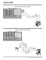
Страница 12: ...enting Systems The shaded areas in the diagram below show all allowable combinations of verti cal runs with horizontal terminations Maximum one 90O elbow two 45o elbows equal one 90o elbow Propane and Natural Gas Residential Manufactured and Mobile Homes Installations The venting arrangements diagrammed below have a min of 75 flue loss efficiency with Fan Off as required for manufactured homes Act...

Страница 13: ... Pipe Restrictor po sition A Venting Arrangements Straight Horizontal Termination at a De Rated BTU The diagrams show all allowable combi nations of straight horizontal termina tion using Rigid Pipe Restrictor position A Refer to page 27 for de rating in structions INSTALLATION If this is an outside corner the minimum distance between the vent and the outside corner is 6 15cm See F on the diagram ...

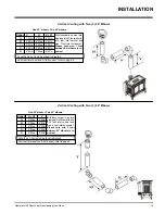
Страница 14: ...ength is 30 feet with min of 9 feet total vertical and max 8 feet total horizontal Please note min 1 foot between 90o elbows is required With these options maxi mum total pipe length is 30 feet with minimum of 8 feet total vertical and maximum 8 feet total horizontal Please note minimum 1 foot between 90o elbows is required INSTALLATION One 90o elbow Two 45o elbows One 90o elbow Two 45o elbows Ven...

Страница 15: ...ease note min 1 foot between 90o elbows is re quired Option H H1 V A 2 Max 2 Min B 3 Max 3 Min C 4 Max 4 Min D 5 Max 5 Min E 6 Max 6 Min Withtheseoptions max total pipelengthis30feetwithmin of 6 feet total vertical and max 6 feet total horizontal Please note min 1 foot between 90o elbows is re quired INSTALLATION One 90o elbow Two 45o elbows One 90o elbow Two 45o elbows Vent restrictor position A ...

Страница 16: ... Arrangements chart below for minimum and maximum flue lengths See chart below for minimumdistancesfromroof Periodicallycheck that the vent is unrestricted Masonry chimneys may take various contours which the flexible liner will accommodate However keep the flexible liner as straight as possible avoid unnecessary bending The Air Intake pipe must be attached to the inlet air collar of the terminati...

Страница 17: ... with the 45o elbow will seat onto both the starter collar and the 90o elbow Crimped sec tionofrigidpipeseatsintothe90o elbow Only cut the uncrimped side of pipe Dismantle all pipe sections including vent terminal 2 Assemble a trial fit to determine the ver tical center line for the vent termination a Cuta9 1 2 x9 1 2 241mmx241mm square hole on both the interior and exterior wall INSTALLATION DV S...

Страница 18: ... fit of the liner onto the 4 dia starter collar 8 Cut the 4 dia flex liner to the desired size Hint leaveanextra12 to16 oflength this willmakethefinalassemblyeasiertowork with 9 Securethe4 dia flexlinertothe4 adapter with Mill Pac and 3 of the 8 x 1 2 screws stainless steel 10 Slide the decorative Thimble Cover over thepipesectionsandsecurewith4screws 8 x 1 1 2 drill point black to the wall 11 Sli...

Страница 19: ...aces with insu lation Theminimumclearancerequirementsbetween the outer wall of the vent pipe and nearby combustible surfaces is 1 1 4 inch Be sure to check the vent termination clearance require ments from decks windows soffits gas regulators air supply inlets and public walk ways as specified in the Exterior Vent Ter minal Locations on page 9 and in your local building codes To determine the leng...

Страница 20: ...flue outlet A twist lock appli ance adapter is installed on the unit at the factory Assemble the desiredcombi nation of pipe andelbowsto the appliance adapter with pipe seams oriented to b Horizontal runs of vent must be sup portedeverythreefeet Wallstrapsare available for this purpose c Snorkel Terminations For installations requiring a vertical rise on the exterior of the building 14 inch and 36...

Страница 21: ...le in the center of the 10 square and attach with wood screws 8 Slide the decorative wall thimble up to the wall surface being careful not to scratch thepaintandattachwithscrewsprovided Apply decorative brass or chrome trim if desired See diagram 6 DURA VENT VERTICAL TERMINATION 1 Maintain the 1 1 4 clearances air spaces to combustibles when passing through ceilings walls roofs enclosures atticraf...

Страница 22: ...metheholeasshownindiagram 9 Hint Apply the sealant Mill Pac and or high tem perature sili cone to the out er pipe before connecting the inner pipe INSTALLATION 4 Assemblethedesiredlengthsofblackpipe and elbows necessary to reach from the appliance adapter up though the Round Support Box Insure that all pipes and elbow connections are in the fully twist locked position and sealed Diagram 10 The upp...

Страница 23: ...red in place and sealed before installing a Direct Vent system within the chimney If the appliance shuts off during opera tion contact a qualified service person to determine if a negative pressure and or leaky chimney condition exists Do not operate the appliance until the problem is corrected Appoved for US Installations Only The use of an existing chimney as an air intake is not covered under t...

Страница 24: ...nicipalities have addi tional local codes it is always best to consult with your local authorities and the CAN CGA B149 installation codes ForUSAinstallationsfollowlocalcodesand or the current National Fuel Gas Code ANSI Z223 1 When using copper or flex connectors use onlyapprovedfittings Alwaysprovideaunion sothatgaslinescanbeeasilydisconnectedfor burner and or valve servicing Flare nuts for copp...

Страница 25: ...ration controls is NOT cov ered under warranty Note Aeration Adjustment should only be performed by an authorized Hampton Installer at the time of installation or service 4 Light the pilot and turn the valve to ON position Read manometer 5 The pressure check should be carried out with the unit burning and the setting should be within the limits specified on the safety label 6 Whenfinishedreadingma...

Страница 26: ...ceyellow NaturalGas labelwithred Propane label 13 Check for gas leaks 14 Check inlet and outlet pressures 15 Check operation of flame control 16 Check for proper flame appearance and glow on logs 7 Unscrewthepilot orificewiththeallenkey and replace with the LP pilot orifice in the kit 4 Remove and discard the 3 pressure regu lator mounting screws A pressure regu lator tower B and diaphragm C 5 Ins...

Страница 27: ...ce 52 Propane 1 918 149 Decal Converted to 28 500 Btu 1 918 148 Instruction Sheet 1 Shut off the gas supply 2 Openthefrontdoor Carefullyremovethelogsandlavarock Refer to manual for more detailed instructions 3 Remove burner by removing 2 screws sliding the burner to the left and lift out See diagram below Burner Orifice Note Use a magnetic type screwdriver if possible 4 Remove Rear Log Bracket by ...

Страница 28: ...rews and push the vent restrictor plate to the correct position Tighten the screws Vent Restrictor setting at Low Btu for Straight Horizontal Venting 11 Attach the label This unit has been con vertedto ontopoftheSerial decalover the higher Btu information 12 Check for gas leaks 13 Check inlet and outlet pressures 14 Checkoperationofflamecontrol Checkfor properflameappearanceandglowonlogs OPTIONAL ...

Страница 29: ...tRightLogG 02 48on LogF 02 47andpushthebottomrightedge against the bracket on the burner tray G 02 48 12 Test fire to ensure proper light off make sure flame flows smoothly from one end of burner to the other If there is any flame hesitation check that area for any block age of the burner port F 0 2 4 7 E 02 45 A 02 43 G 02 48 D 0 2 4 6 B 02 56 C 02 44 Cutout Pin D 02 46 B 02 56 A 02 43 7 Place th...

Страница 30: ...from the sides of the Front Casting 3 Fasten the Right Door to the 2 right hinges 2 screws per hinge Repeat for the Left Door TILE INSET INSTALLATION Side Tile Inset 1 Slide the Standard Side Tile Inset out to wards the back of the unit 2 Slide the Optional Side Tile Inset into the side panel over the spring clip 3 Repeat for other side Top Tile Inset 1 Lift the Cast Top off the unit 5 Replace the...

Страница 31: ...f of the stove 2 Release the catches on the left and right side of the stove that secure the glass 3 Remove the glass by sliding it up and out 4 Pull all four door hinges out from the sides of the front casting Release catch by pulling up 5 Use a 7 16 wrench to remove the screws that secure the door hinges Remove screws ...

Страница 32: ... directly intoaproperlygroundedthree prong receptacle Donotcutorremovethe grounding prong from this plug OPTIONAL REMOTE CONTROL Use the Hampton Remote Control Kit approved forthisunit Useofothersystemsmayvoidyour warranty The remote control kit comes with a hand held transmitter a receiver and a wall mounting plate INSTALLATION OPTIONAL WALL THERMOSTAT A wall thermostat may be installed if desire...

Страница 33: ...ndon again without a minimum of a 60 second wait 1 Choose a convenient location on the wall to install the receiver and the receptacle box protectionfromextremeheatisveryimpor tant Run wires from the fireplace to that location use Thermostat Wire Table 2 Connectthewiresasperthewiringdiagram below CAUTION Do not connect the millivolt remote control wires to the 120V wires 3 Install3AAAalkalinebatte...

Страница 34: ...d Thefanwillturnonasthestove comes up to operating temperature After the unit has been turned off and the unit cooled to below a useful heat output range the fan will shut off automatically ADJUSTING FLAME HEIGHT Yourheaterhasanadjustableflametotailorthe look and heat output to your specific needs It is adjusted by turning the flame adjustment dial on the gas control valve Turn clockwise to adjust...

Страница 35: ... Body Firebox Different types and thicknesses of steel will expandandcontractatdifferentratesresulting in some cracking and ticking sounds will be heard throughout the cycling process SHOULD BE ALERTED TO THE HAZARDS OF HIGH SURFACE TEMPERATURE AND SHOULD STAY AWAY TO AVOID BURNS ORCLOTHINGIGNITION YOUNG CHILDREN SHOULD BE CARE FULLYSUPERVISEDWHENTHEY ARE IN THE SAME ROOM AS THE APPLIANCE DO NOT U...

Страница 36: ...eunitshouldneverbeusedwithbrokenlogs Turn off the gas valve and allow the unit to cool before opening door to carefully remove the logs The pilot light generates enough heat to burn someone If for any reason a log should need replacement you must use the proper replacement log The position of these logs must be as shown in the diagram under Log Installation Note Improper positioning of logs may cr...

Страница 37: ...with an 11 mm wrench 16 Remove valve to orifice nut with a 13 16 wrench 17 Remove inlet pipe with pipe wrench Note orientation of 90o elbow 18 Removetwo 2 phillipsheadM5screwson each side of the valve 19 Remove valve and remove gas out 90o brass fitting Note orientation of fitting INSTALLING VALVE ASSEMBLY 1 To install a new valve assembly reverse instructions for removing valve See assembly steps...

Страница 38: ...Insert Bracket 49 740 063 Side Insert Spring Top Relief Door Assembly Part Description Part Description Part Description Passage 56 W842051 Gasket Upper Air Passage Top 57 W260108 Gasket Upper Air Passage Bottom 58 630 009 Gasket Lower Air Passage 59 Upper Air Passage Assy 61 945F Direct Vent Adaptor Rear Panel Assembly 114 Wire Tie Wrap 115 Wire Tie Mount Button 118 910 897 HighTemperatureWireHar...

Страница 39: ...68 W840470 Pilot Assembly Gasket 69 Valve Shield 70 Valve Bracket 71 Valve Gasket 72 Front Support 73 730 528 Rear Log Bracket Assy 75 402 935 Log Set 740 572 Ember Package 78 730 550 Burner Assy 740 546 Base Assembly 79 Base Plate 80 Brick Panel Right Side 81 Brick Panel Left Side 82 Brick Panel Back 83 400 090 Brick Clip 84 948 042 Hinge of Valve Access Door 85 260 056 Valve Access Door 86 260 5...

Страница 40: ...______________________________________________________ ______________________________________________________ _______________________________________________________________ ___________________________________________________________ __________________________________________________________ ____________________________________________________________ ______________________________________________...

Страница 41: ...______________________________________________________ ______________________________________________________ _______________________________________________________________ ___________________________________________________________ __________________________________________________________ ____________________________________________________________ ______________________________________________...

Страница 42: ...______________________________________________________ ______________________________________________________ _______________________________________________________________ ___________________________________________________________ __________________________________________________________ ____________________________________________________________ ______________________________________________...

Страница 43: ...eturned to FPI and evaluated for manufacturer defect The authorized selling dealer is responsible for all in field service work carried out on your Waterford product FPI will not be liable for results or costs of workmanship from unauthorized service persons or dealers At all times FPI reserves the right to inspect product in the field which is claimed to be defective All claims must be submitted ...

Страница 44: ..._________________________________________________ Printed in Canada Hampton is a trademark of FPI Fireplace Products International Ltd Hampton fireplace products are designed with reliability and simplicity in mind In addition our internalQualityAssuranceTeamcarefullyinspects each unit thoroughly before it leaves our door FPIFireplaceProductsInternationalLtd ispleased to extend this Limited Lifeti...

Отзывы: