1
Subject to change without notice
measure directly in digital circuits because of
this impedance which will influence the circuit
behavior. As a minimum the measurement results
are false. Consequently, for the measurement in
digital circuits a high impedance probe is required
which does not load the circuit and convert the
signal to a 50 Ohms system over a wide frequency
range.
The following measurement results were
measured with the High Impedance Probe con-
nected to a Spectrum Analyzer and with a digital
scope.
In principle, it is easy to assume that it is possible
to select signal-line filters from catalog values.
Well-known manufacturers offer filters with
measurement data in the time- and frequency-
domain. Unfortunately, the filter data is performed
with an entirely resistive load and therefore the
data looks very good. However, in practice an
entirely resistive circuit seldom exists. Therefore,
the filters must be evaluated when installed in a
practical circuit. It is then observed that the per-
formance of the filters is not as promised in the
catalog. This shall be demonstrated with a series
of illustrative examples which are measured in
circuits of the 7 ACT family. The gates are always
operated with a 5MHz frequency.
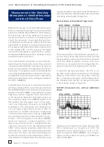
Figure 1 shows the time and frequency domain
outputs of such a gate which is mounted on a
printed circuit and is not loaded. The frequency
spectrum is measurable to 1,000MHz. In fact, it
extends even above 1,000MHz, but for compari-
son purposes all measurements are scaled only
1,000MHz. In the time domain relatively strong
over and under shoot and fast risetimes are ob-
servable. This signal is very poor relative to the
EMC characteristics. The excessive bandwidth
permits radiation to take place on relatively small
printed circuit boards. When this signal is con-
ducted to other parts, it is especially important
to limit the spectrum to avoid excessive shielding
structures.
As a first measure to limit the spectrum, a resistor
is recommended between the gate output and the
conductor connection. The conductor is simulated
by an individual gate input to obtain a realistic
circuit. The connection and the conductor length
must correspond to the actual relationship to
P r a c t i c a l S e l e c t i o n o f S i g n a l - L i n e F i l t e r s
Figure 3
Figure 2


