9
Subject to change without notice
P r a c t i c a l E M I p r o b l e m s
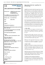
Picture 3: Signal directly close to the Vccpin of
a74AC00.
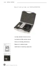
Picture 4: Comparable signal taken in a power-
distribution system with 2 stage damping.
In contrast to this picture shows the same
signal pick-off point, but now the IC is powered
by a two-stage damped distribution system. The
V
cc
pin is connected to the V
cc
layer via a large
bandwidth filter choke, also this layer is damped
by a layer of carbon. The reduction of amplitude is
obvious. Just using this probe allows to determine
the effect of the measure without the use of any
further equipment.
Signal at clock generator output
The last example shows the signal taken from
a clock distribution point on a“Europe” size EC
board. The signal is taken directly from the output
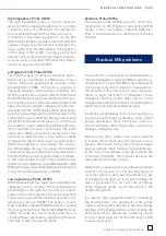
of the clock generator. Picture 5 shows the signal
without any EMI damping measures, a very large
amplitude signal of 60mV is measured.
Picture 5: µH field probe signal taken from a cir-
cuit with no EMI prevention measures taken.
A popular means of improving the situationis the
insertion of a series resistance direct-ly at the
output of the clock generator. In this case 8 Ohms
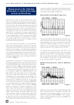
were used. Picture 6 showsthe result: the signal
amplitude is cut by half. The effect of the measure
is visible immediately.
Picture 6: A series resistor at the output of the
clockgenerator cuts the amplitude in half.


