38
Setting the configuration
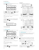
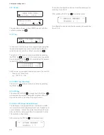
* LEV. OFFSET MENU *
Att. On Off
On
Activation of the attenuator compensation. Output level is
updated according to the attenuation value.
Off
Deactivation of the attenuator compensation. Output level
is updated.
Att.
Gives access to the menu permitting the edition of the ex-
ternal attenuator value. When activated the actual level
takes into account the attenuation value of the external at-
tenuator. The output level at the output of the generator is:
P
set
+Att, with P
set
= programmed output level in dBm, Att
= attenuation value in dB.
If the actual programmed level is above P
max
+Att the out-
put level is automatically reduced in order that the out-
put level of the generator never exceeds its maximum level
(+13 dBm with deactivated amplitude modulation (AM) or
+7 dBm with activated amplitude modulation). When tur-
ning OFF the attenuator correction, if the actual level is be-
low –135 dBm the level is automatically set to –135 dBm.
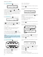
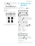
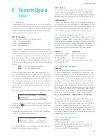
Att.: 20.0dB
– stp + cur
The settings of the Level Offset will be save into non-vola-
tile memory automatically. To escape from this menu wit-
hout saving by pressing PREV. key.
The attenuation of the external attenuator can be ente-
red directly using the keypad. Press dBm unit key after en-
tering the value. The value can be increased or decrea-
sed with 1 dB step using – and + step key. The value can
also be modified using the encoder and cursor keys. The
output is updated accordingly when the attenuator va-
lue is changed. The allowed attenuation range is 0.0 dB to
30.0 dB. Press PREV. key to return to the main Level Off-
set menu.
Using the Level Offset
When setting the output level the displayed level takes into
account the external attenuator. The allowable level range
is decreased by the amount of the attenuation value.
Example:
With 20.0 dB attenuator and deactivated ampli-
tude modulation (AM OFF) the level can be adjusted from
–147 dBm to –7 dBm. When the attenuator compensation
is active the dot symbol is replaced by a colon character in
the amplitude display:
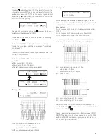
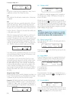
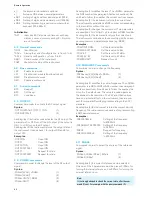
Level: -140:0 dBm
– stp + cur
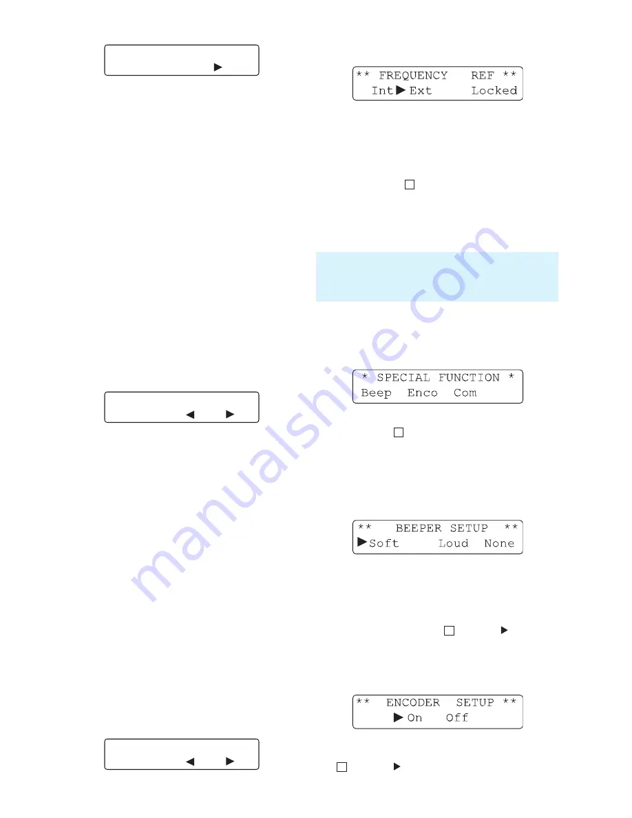
5.4 Reference REF
The HM8134-3 is basically equipped with a temperature
controlled crystal oscillator (TCXO) with a reference fre-
quency of 10 MHz.
After each access to the configruation menu by using the
context sensitive keys
5
, the phaselock loop starts a test of
the reference oscillator (locked or unlocked). The external re-
ference frequency must be applied to the REF. INPUT 10 MHz
and the internal reference frequency is available on the REF.
OUPUT 10 MHz at the rear panel.
5.5 Special function SFC
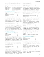
After selecting the SFC option in the configuration menu,
the display shows:
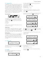
Disp
The special function can be selected by pressing the con-
text sensitive keys
5
.
5.6 Beeper
BEEP
The built-in beeper will react to every key stroke and will
indicate any operation errors. The activation and the ad-
just-ment of the volume is done in the beeper menu:
❙Soft (soft sound)
❙Loud (loud sound)
❙None (no sound)
The characteristic of the beeper can be selected by pres-
sing the context sensitive keys
5
. A triangle points out
the current state.
5.7 Encoder
ENCO
In this menu the activation of the rotary control is done by
selecting the ON or OFF option with the context sensitive
keys
5
. A triangle points out the current state.
Caution:
If the reference frequency from an external source is not within
specifications, the error message error will be displayed. In this
case the internal reference will be automatically activated.
Содержание HM8134-3
Страница 47: ...47 Remote Operation...
Страница 50: ...50 Flow Charts Flow Charts Function selection Step control Phi Phi Phi...
Страница 51: ...51 Flow Charts Amplitude Modulation Control FSK PSK GATE...
Страница 52: ...52 Flow Charts Phase Modulation Control FSK PSK GATE...
Страница 53: ...53 Flow Charts Frequency Modulation Control FSK PSK GATE...
Страница 56: ...56 Flow Charts Gate Control FSK PSK GATE...

