background image

44

Remote Operation

Sending line (4) the instrument returns the FM source. The 
instrument sends back the strings INT or EXT (not INTERN 
or EXTERN). If the FM is turned off, the string INT is sent 
back because the internal source is the default setting for 
the command FM:STAT 1 .

:FM:INTern:FREQuency <NUM>   

(5)

:FM:INTern:FREQuency? 

  (6)

Sending line (5) the frequency of the internal modulation 
signal can be changed. The <NUM> parameter is a NR1 or 
NR2 or NR3 number (see paragraph Syntax conventions). 
No unit has to follow the number, Hz unit is the default 
one. The value is rounded  to the resolution.
Sending line (6) the instrument returns the current modula-
tion frequency. The instrument sends back a string repre-
senting a NR3 decimal number.

:FM:INTern:SHAPe  SIN | SQU 


(7)

:FM:INTern:SHAPe? 

  (8)

Sending line (7) the shape of the internal modulation signal 
can be changed. The parameters are: SIN for a sine signal, 
SQU for square. 
Sending line (8) the instrument returns the current shape. 
The instrument sends back the same strings as the corres-
ponding command parameters above.

:FM:STATe   0 | OFF | 1 | ON 


(9)

:FM:STATe? 

   (10)

Sending line (9) the FM can be turned on or off. The FM is 
turned on by sending parameters 1 or ON and the parame-
ters 0 or OFF turn the modulation off (if present). 
Sending line (10) the instrument returns the current FM 
state. The instrument sends back 0, if no FM is in pro-
gress, and 1, if FM is present.

:FM:EXTern:COUPling AC | DC 


(13)

:FM:EXTern:COUPling? 

  (14)

Sending line (13) the external FM modulation is set to AC 
or DC mode. 
Sending line (14) the instrument returns the current state. 
The instrument sends back the same strings as the corres-
ponding command parameters above.

Example:   

FM:INT:FREQ  9E+3;  SHAP  SIN;   DEV  150E+3; STAT  ON

6.15  PM (Phase Modulation)

Commands in order to modify PM parameters

Syntax:

:PM[:DEViation]  <NUM>  


(1)

:PM[:DEViation]? 

   (2)

Sending line (1) the PM deviation can be modified. The 
<NUM> parameter is a NR2 number (see paragraph Syn-
tax conven-tions). No unit has to follow the number, the 
current unit is the default one. If the value has an accuracy 

higher than the resolution, the number is rounded to the 
corresponding digit.
Sending line (2) the instrument returns the current PM de-
viation. The instrument sends back a string representing a 
NR2 decimal number (without unit).
  
:PM:UNIT RAD | DEG 


(3)

:PM:UNIT? 

   (4)

Sending line (3) the current unit of the phase can be 
changed. Two parameters are possible: RAD for radian or 
DEG for degree. 
Sending line (4) the instrument returns the current unit. 
The instrument sends back the same strings as the corres-
ponding command parameters above.

:PM:SOURce  INTern | EXTern 


(5)

:PM:SOURce? 

   (6)

Sending line (5) the modulation source can be selected 
and at the same time the PM is turned on. 
Sending line (6) the instrument returns the PM source. The 
instrument sends back the strings INT or EXT (not INTERN 
or EXTERN). If the PM is turned off, the string INT is sent 
back because the internal source is the default setting for 
the PM:STAT 1 command.

:PM:INTern:FREQuency <NUM>   

(7)

:PM:INTern:FREQuency? 

  (8)

Sending line (7) the frequency of the internal modulation 
signal can be changed. The <NUM> parameter is a NR1 or 
NR2 or NR3 number (see paragraph Syntax conventions). 
No unit has to follow the number, Hz unit is the default 
one. The value is rounded to the resolution. 
Sending line (8) the instrument  returns the current modu-
lation frequency. The instrument sends back a string repre-
senting a NR3 decimal number.

:PM:INTern:SHAPe SIN | SQU 


(9)

:PM:INTern:SHAPe? 

  (10)

Sending line (9) the shape of the internal modulation signal 
can be changed. The parameters are: SIN for a sine signal, 
SQU for square. 
Sending line (10) the instrument returns the current shape. 
The instrument sends back the same strings as the corres-
ponding command parameters above.

:PM:STATe 0 | OFF | 1 | ON 


(11)

:PM:STATe? 

   (12)

Sending line (11) the PM can be turned on or off. The PM is 
turned on by sending the parameters 1 or ON and it is tur-
ned off by sending 0 or OFF (if present). 
Sending line (12) the instrument returns the current PM 
state. The instrument sends back 0, if no PM is in pro-
gress, and 1, if PM is present.

Содержание HM8134-3

Страница 1: ...odulationsarten AM FM Puls Phase FSK PSK R Interne Modulation 10Hz bis 150kHz Sinus Rechteck Dreieck Rampe R Externer Ref Eingang Ausgang 10MHz ber BNC Anschluss R HM8134 3 TCXO Temperaturstabilit t 0...

Страница 2: ...ngen beeinflussen die Einhaltung der vorgegebenen Grenzwerte in erheblicher Weise Die verwendeten Leitungen sind jedoch je nach An wendungsbereich unterschiedlich Im praktischen Messbe trieb sind dahe...

Страница 3: ...uration 13 5 1 Schrittauswahl 13 5 2 MENU Taste 13 5 3 Offset Korrektur 14 5 4 Referenz REF 14 5 5 Spezialfunktionen SfC 14 5 6 Beeper BeeP 14 5 7 Drehgeber Enco Encoder 15 5 8 Interface COM 15 5 9 Di...

Страница 4: ...werden 1 5 Sicherheitshinweise Dieses Ger t wurde gem VDE0411 Teil1 Sicherheitsbe stimmungen f r elektrische Mess Steuer Regel und La borger te gebaut und gepr ft und hat das Werk in sicher heitstechn...

Страница 5: ...er Reinigungsmittel kann die Beschriftung oder Kunststoff und Lackober chen angreifen Die L ftungsl cher und die K hlk rper des Ger tes d rfen nicht abgedeckt werden Das Produkt darf nur von daf r aut...

Страница 6: ...chen Hintergrundbe leuchtete LCD Abb 2 1 Frontansicht des HM8134 3 1 13 10 8 2 3 4 5 6 7 9 11 12 14 15 Abb 2 2 R ckansicht des HM8134 3 23 20 21 22 17 18 16 19 9 FUNCTIONS Funktionstasten und LEDs 10...

Страница 7: ...aufgeru fen werden Ger t ausschalten Ger t einschalten und solange die ESC Taste dr cken bis einige Beeps zu h ren sind Im Zweifelsfalle ist das eine hilfreiche berwachungsfunktion 3 4 Display Die An...

Страница 8: ...3 Digit 3 9 Wahl der Modulationsart Nach Bet tigung der MOD Funktionstaste 9 zeigt das Display MODULATION MENU AM FM PM MODULATION MENU FSK PSK GATE Achtung Bei eingeschalteter Amplitudenmodulation wi...

Страница 9: ...on 1 1ms Periodendauer 2 5ms Fmod 400Hz CH2 Moduliertes Signal Frequenzhub 2kHz Beispiel 2 In diesem Beispiel besteht das externe Modulationssignal aus einem TRINARY Code bestehend aus 9 Bits 1 Bit be...

Страница 10: ...ste 3 wird zum vorherigen Men punkt zur ckgeschaltet Mit der ESC Taste 13 wird zum Haupt Display umgeschaltet Beispiel 3 F r AM Sinus Modulationsgrad 50 erh lt man Beispiel 4 F r AM Rechteck Modulatio...

Страница 11: ...zhub 80kHz 4 3 Phasenmodulation PM Nach Auswahl der Option DEV PM MENU mittels der kontextsensitiven Tasten 9 zeigt das Display Ein neuer Funktionswert kann ber die Tastatur 11 mit dem Drehknopf 10 od...

Страница 12: ...k0 bzw Psk1 kann ber die Tastatur 11 mit dem Drehgeber 10 oder mit den kontextsensitiven Tasten 5 eingestellt werden Die Bedie nung erfolgt wie im Abschnitt 3 6 EINSTELLUNG DER PA RAMETER beschrieben...

Страница 13: ...EP MENU FM Phi D Mittels der kontextsensitiven Tasten 5 wird die entspre chende Option ausgew hlt Ist der Parameter schon aus gew hlt kann mit der STEP Taste 9 die Schrittart direkt gew hlt werden Bei...

Страница 14: ...nativ kann der Wert auch mit Hilfe des Drehgebers oder den Cursor Tasten eingestellt werden Wenn der D mpfungswert ge ndert wird aktuali siert sich der Ausgangspegel entsprechend Der zul ssige Regelbe...

Страница 15: ...Bei Be darf kann die Baudrate ge ndert werden Verbinden Sie den HM8134 3 mit einem USB Kabel mit Ihrem PC und installieren Sie die Treiber der USB Schnittstelle wie im Handbuch der USB Schnittstelle...

Страница 16: ...ch wie folgt berechnet Step Count Step Time hier 100 0 1s 10s 5 13 PREV Taste Previous Mit der PREV Taste 3 wird zum vorherigen Men punkt zur ckgeschaltet 5 14 ON Taste Der Signalausgang RF OUTPUT 14...

Страница 17: ...nn die Baudrate ge ndert werden Verbinden Sie den HM8134 3 mit einem USB Kabel mit Ihrem PC und installieren Sie die Treiber der USB Schnittstelle wie im Handbuch der USB Schnittstelle HO820 beschrieb...

Страница 18: ...aktuellen Statusab frage Das Instrument sendet 0 bei nicht aktiviertem RF Ausgang und sendet 1 bei aktiviertem RF Ausgang Beispiele OUTP ON Ausgang Ein OUTP 1 Ausgang Ein OUTPUT ON Ausgang Ein OUTPUT...

Страница 19: ...cher NR2 Da ten string siehe Abschnitt Syntaxkonvention Dem Daten string folgt automatisch die Bezeichnung der Einheit Ist die Aufl sung 0 1 wird der Wert zur n chst h heren Stelle hin aufgerundet Bef...

Страница 20: ...ehlszeile 8 dient der aktuellen Signalformabfrage Das Instrument antwortet mit dem entsprechenden Daten string z B SIN FM STATe 0 OFF 1 ON 9 FM STATe 10 Befehlszeile 9 dient der FM Modulationswahl Die...

Страница 21: ...s Instrument sendet den Datenstring EXT nicht EXTERN FSKey F0 NUM 3 FSKey F0 4 FSKey F1 NUM 5 FSKey F1 6 Die Befehlszeilen 3 und 5 dienen der FSK Frequenzein stellung F0 bzw F1 Der NUM Parameter ist e...

Страница 22: ...16E 6 FREQ STOP 1 2E 9 FREQ MODE SWE 6 19 Befehle SYSTEM Syntax SYSTem ERRor Diese Befehlszeile dient der Abfrage des aktuellen Fehler codes Wenn mehrere Fehler aufgetreten sind wird der zu erst gemel...

Страница 23: ...Bereich 10Hz 20kHz 82 FM oder PM Frequenzmodulation Fehler erlaubter Bereich 10Hz 100kHz 90 PM Frequenzhub Fehler erlaubter Bereich 0 rad 3 14 rad 91 PM Frequenzhub Fehler erlaubter Bereich 0 rad 10...

Страница 24: ...tliche PM Pulsmodulation Quelle extern Ger ter ckseite Dynamikumfang 80dB Anstiegs Abfallzeiten 50ns 7 Technische Daten Technische Daten 1 2GHz HF Synthesizer HM8134 3 Alle Angaben bei 23 C nach einer...

Страница 25: ...tstelle USB RS 232 HO820 optional HO880 IEEE 488 GPIB Konfigurationsspeicher 10 Schutzart Schutzklasse I EN61010 1 Netzanschluss 115 230V 10 50 60Hz CAT II Leistungsaufnahme ca 40VA Arbeitstemperatur...

Страница 26: ...s must not leave the premises All signal con nections must be shielded e g coax such as RG58 U With signal generators double shielded cables are man datory It is especially important to establish good...

Страница 27: ...36 4 5 PSK Modulation 36 4 6 GATE modulation 36 5 Setting the configuration 37 5 1 Selecting step 37 5 2 MENU key 37 5 3 Level Offset 37 5 4 Reference REF 38 5 5 Special function Sfc 38 5 6 Beeper Bee...

Страница 28: ...r to preserve safety and guarantee operation without any danger to the opera tor According to safety class 1 requirements all parts of the housing and the chassis are connected to the safety ground te...

Страница 29: ...faces 1 9 Line voltage selector The instrument is destined for operation on 115 or 230 V mains 50 60 Hz The proper line voltage is selected with the line voltage selector It is necessary to change the...

Страница 30: ...ions keys and LEDs 10 Rotary knob Dial for setting all parameters 11 NUMERIC KEYPAD Input parameters with unit validation 12 ON Key for activation the output 13 ESC Escape Cancels the current display...

Страница 31: ...off the unit Switch on the unit and hold the ESC key until you hear several beeps This procedure is especially suited in case of doubt 3 4 Display This display shows the frequency and the level of th...

Страница 32: ...eys 5 corresponding to AM Amplitude modulation FM Frequency modulation PM Phase modulation FSK Frequency shift keying Caution If the AM modulation is activated the instrument automatically limits the...

Страница 33: ...n first pulse width 150s second pulse width 1 1ms period 2 5ms Fmod 400Hz CH2 moduled signal deviation 2kHz Example 2 In this example the external modulation signal is a tri nary code composed of 9 bi...

Страница 34: ...vious menu is possible by pressing the PREV key 3 and the return to the main display by pressing the ESC key 13 Example 3 For AM sine depth 50 the display shows Example 4 For AM square depth 50 the di...

Страница 35: ...dulated signal deviation 80kHz 4 3 Phase modulation PM After selecting DEV PM MEMU using the context sensi tive keys 5 the display shows A new value of this deviation can be entered from the data keyp...

Страница 36: ...modified by the rotary knob 10 or by one of the four context sensitive keys 5 For more details refer to paragraph 3 6 SETTING PARAMETERS The skip phase Psk0 Psk1 or Psk1 Psk0 may be set from 3 14 rad...

Страница 37: ...an directly be modified by pressing the STEP function key 9 Press again the STEP key to go back to previous display A new value of the step can be entered from the data key pad 11 or modified by the d...

Страница 38: ...the displayed level takes into account the external attenuator The allowable level range is decreased by the amount of the attenuation value Example With 20 0dB attenuator and deactivated ampli tude...

Страница 39: ...to the desired value The adress is changed at the inter face on the rear panel Do this settings only before star ting the instrument It is not possible when the instrument is running 5 9 Display LCD D...

Страница 40: ...the result of Step Count Step Time e g 100 0 1s 10s 5 13 PREV key Previous The return to the previous menu is possible by pressing the PREV key 3 5 14 ON key The output RF OUTPUT 14 is only active if...

Страница 41: ...ssary to set the GPIB adress of the HM8134 3 to the desired value The adress is changed at the interface on the rear panel Do this settings only before starting the instru ment It is not possible when...

Страница 42: ...strument returns the current level The instruments sends back a NR2 number corresponding to the resolution without the unit Sending line 3 changes the current unit Two parameters are possible V for Vo...

Страница 43: ...eturns the source modu lation The instrument sends back the strings INT or EXT not INTERN or EXTERN If the AM is turned off the string INT is sent back because this source is the default setting for t...

Страница 44: ...ven tions No unit has to follow the number the current unit is the default one If the value has an accuracy higher than the resolution the number is rounded to the corresponding digit Sending line 2 t...

Страница 45: ...ument returns the PSK source It sends back the string EXT not EXTERN PSKey PH0 NUM 3 PSKey PH0 4 PSKey PH1 NUM 5 PSKey PH1 6 Sending line 3 and 5 the two phases PH0 and PH1 can be changed The NUM para...

Страница 46: ...ame group may be shorter without repea ting all the tree descriptions If the next command does not belong to the same tree it is necessary to specify the root 6 20 Error codes and their meaning 00 No...

Страница 47: ...47 Remote Operation...

Страница 48: ...cy 5 up to 1kHz residual PM Pulse modulation Source external Dynamic range 80dB Rise fall times 50ns 7 Technical Data Technical Data 1 2GHz HF Synthesizer HM8134 3 All data valid at 23 C after 30 minu...

Страница 49: ...ctive functions The synthesizer is protected against reverse power applied to the RF output up to 1W for a 50 source and against any DC source up to 7V The protection disconnects the output until manu...

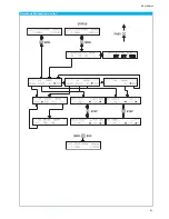
Страница 50: ...50 Flow Charts Flow Charts Function selection Step control Phi Phi Phi...

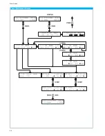
Страница 51: ...51 Flow Charts Amplitude Modulation Control FSK PSK GATE...

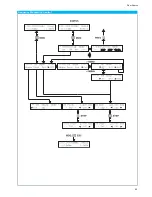
Страница 52: ...52 Flow Charts Phase Modulation Control FSK PSK GATE...

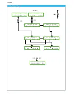
Страница 53: ...53 Flow Charts Frequency Modulation Control FSK PSK GATE...

Страница 54: ...nt MOD STATUS PREV MOD 400 000000MHz FSK 410 000000MHz Ext MODULATION MENU AM FM PM MODULATION MENU FSK PSK GATE FSK PARAMETERS F0 F1 On Off FSK PARAMETERS F0 F1 On Off stp cur Fsk0 512 000000 MHz stp...

Страница 55: ...0dBm REFint MOD STATUS PREV MOD 1200 000000MHz PSK 13 0dBm Ext MODULATION MENU AM FM PM MODULATION MENU FSK PSK GATE PSK PARAMETERS PH0 PH1 On Off PSK PARAMETERS PH0 PH1 On Off stp cur Psk0 10 00rad s...

Страница 56: ...56 Flow Charts Gate Control FSK PSK GATE...

Страница 57: ...7 Flow Charts Main Menu Control Offs Ref Sfc Sweep INTERFACE TYPE SERIAL SERIAL SERIAL INTERFACE TYPE I3E INTERFACE TYPE USB RS232 DEFAULT 4800 NONE 8 1 SERIAL INTERFACE TYPE HO890 DISPLAY ADJUST Disp...

Страница 58: ...1200 000000MHz FIX 13 0dBm REFint MENU STATUS MAIN MENU Ref Sfc Sweep SWEEP MENU PREV Start Stop Time Off SWEEP MENU Start Stop Time On Fstr 16 000000 MHz stp cur Fstp 1200 000000 MHz stp cur SweepTi...

Страница 59: ...9 00 54 Subject to change without notice Tables T a b l e s 54 Subject to change without notice I I VSWR I I VSWR I I VSWR I I VSWR 0 00 1 00 0 25 1 67 0 50 3 00 0 75 7 00 0 01 1 02 0 26 1 70 0 51 3 0...

Страница 60: ...4 1 174 10 4 0 740 6 4 0 467 2 4 0 295 18 3 1 839 14 3 1 160 10 3 0 732 6 3 0 462 2 3 0 291 18 2 1 818 14 2 1 147 10 2 0 724 6 2 0 457 2 2 0 288 18 1 1 797 14 1 1 134 10 1 0 715 6 1 0 451 2 1 0 285 1...

Страница 61: ...1 698 18 2 66 069 14 2 26 303 10 2 10 471 6 2 4 169 2 2 1 660 18 1 64 565 14 1 25 704 10 1 10 233 6 1 4 074 2 1 1 622 18 0 63 096 14 0 25 119 10 0 10 000 6 0 3 981 2 0 1 585 17 9 61 660 13 9 24 547 9...

Страница 62: ...245 6 5 2 113 11 1 3 589 15 7 6 095 20 3 10 351 2 0 1 259 6 6 2 138 11 2 3 631 15 8 6 166 20 4 10 471 2 1 1 274 6 7 2 163 11 3 3 673 15 9 6 237 20 5 10 593 2 2 1 288 6 8 2 188 11 4 3 715 16 0 6 310 2...

Страница 63: ...6 11 3 55 51 355 71 3 55 111 355 12 3 98 52 398 72 3 98 112 398 13 4 47 53 447 73 4 47 113 447 14 5 01 54 501 74 5 01 114 501 15 5 62 55 562 75 5 62 115 562 16 6 31 56 631 76 6 31 116 631 17 7 08 57 7...

Страница 64: ...chwarz com Internet www rohde schwarz com Customer Support www customersupport rohde schwarz com Service www service rohde schwarz com Subject to change Data without tolerance limits is not binding R...

Отзывы: