27
FAULT FINDING
8
8.1
GENERAL
Befor
e looking for a fault condition, check that:
●
The mains electrical supply is tur
ned on.
●
The r
oom thermostat and clock (where fitted) are calling for heat.
Radiators are bled and free of air.
●
The gas ser
vice cock is open.
●
The system is at design pr
essure.
Before attempting any electrical fault finding, always conduct the
preliminary electrical system checks as described in the Instructions
for the British Gas Multimeter, or other similar instrument.
On completion of any service or fault finding operation involving
making or breaking electrical connections, always check for EARTH
CONTINUITY, POLARITY and RESISTANCE TO EARTH.
Detailed procedures for replacing faulty components are described
in section 9 (Parts Replacement).
For further information contact: Halstead Boilers Ltd. Service Help
line: 01926 834834
8.2
DIAGNOSTIC DIGITAL DISPLAY
F
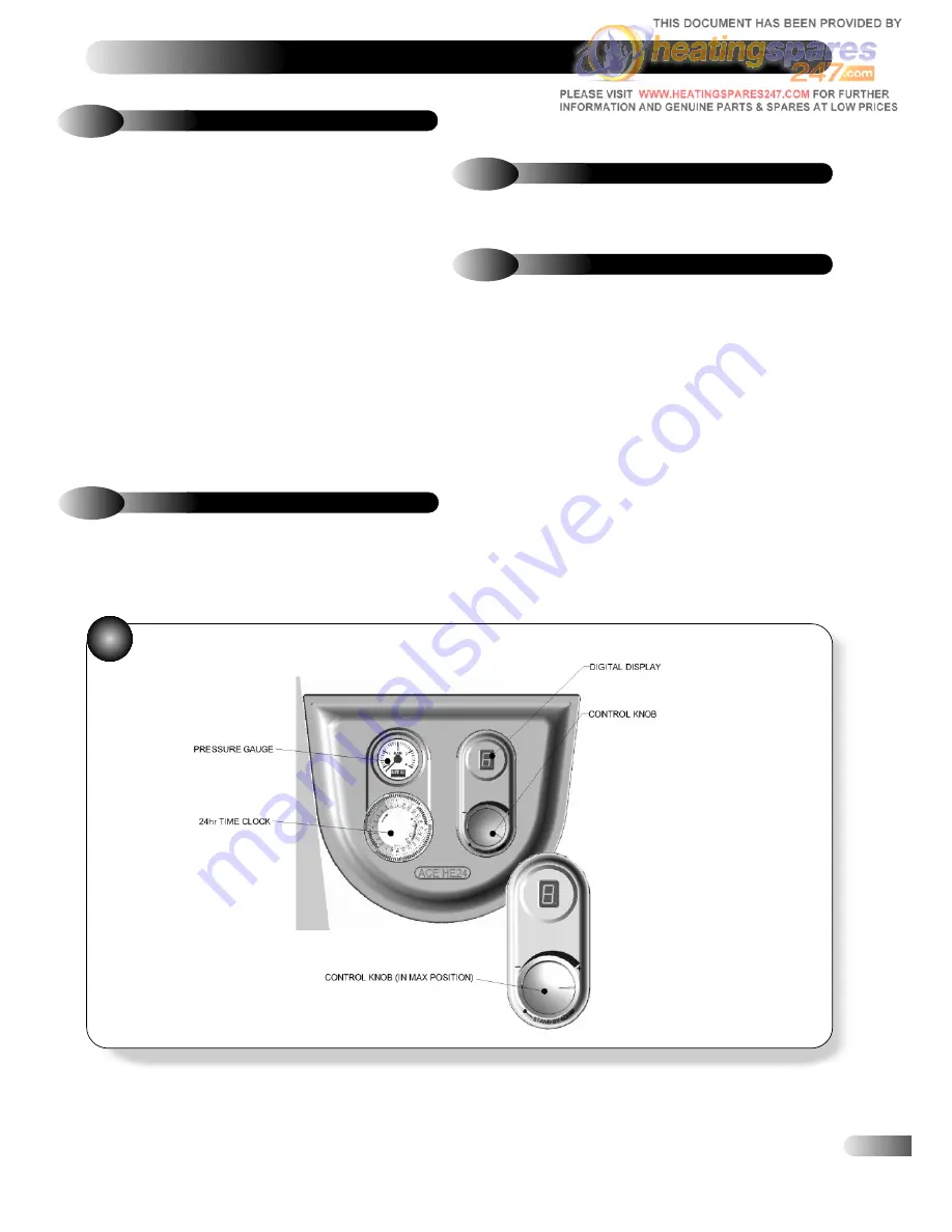
ASCIA PANEL - Refer to Figure 31.
The Digital Display shows er
ror code ‘3’ in a lockout condition.
To RESET the boiler turn the control knob fully anti-clockwise to the
8.3
FAULT FINDING CODES
In the event of the appliance failing to light, r
efer to the
Diagnostics Chart.
30
When the hot water tap is tur
ned on, the control should perform a
series of checks followed by an ignition sequence. Refer to section
5.2.
If the control has powered up correctly but does not respond to a
DHW demand, check the following:
a)
Check that the DHW flow rate at the tap is gr
eater than 2.5
litres/minute.
b)
Check the operation of the DHW flow switch, Figur
e 28.
c)
Check the wir
es to the DHW flow switch.
d)
Check connector X8 is cor
rectly connected to the PCB.
e)
Check for water in the CH system etc.
If DHW temperature fluctuates heavily during a long draw off,
check the plate heat exchanger and the flow switch filters for
debris, clean and replace, (refer to section 6.7 and 9.17).
8.4
DHW FAULT FINDING
RESET/ST
AND-BY position and then back to anywhere between
the ‘+’ and ‘–‘ within TWO seconds.


