Halogen
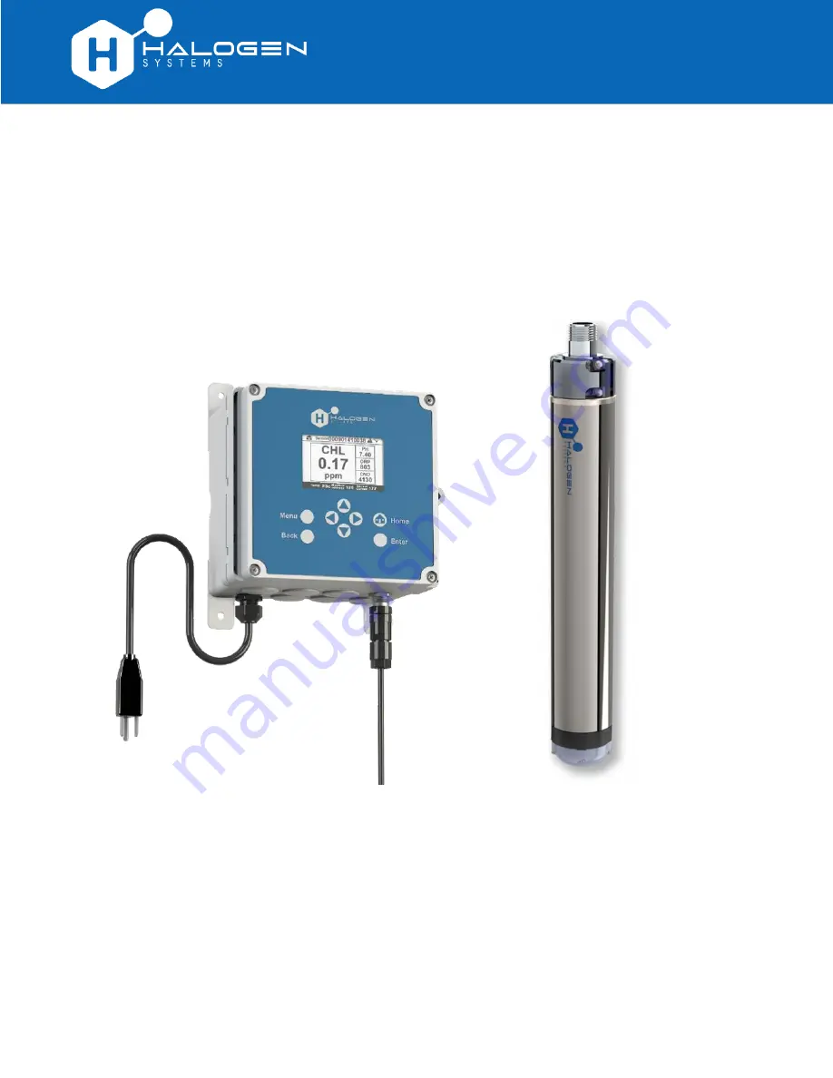
D20 Display/Controller and
MP5 Sensor
Installation Guide
Страница 1: ...Halogen D20 Display Controller and MP5 Sensor Installation Guide...
Страница 2: ...es a hazardous situation that could result in injury or death If on the instrument refer to the instruction manual for operation or safety information Risk of electric shock Indicates components or a...
Страница 3: ...ON OF CONFORMITY Drinking Water Sensors are Tested and certified to NSF ANSI CAN 61 and 372 2020 Certificate date issued 7 23 2021 120VAC Displays Also Tested and Certified to Safety Requirements for...
Страница 4: ...electrical connectors and fittings 6 Connect the 4 20mA wiring 7 Step 3 Set up Halogen sensor 8 Using the Halogen side stream sensor 8 To install the flow cell 9 Positioning the flow cell 9 Connect de...
Страница 5: ...aph below shows a demonstration of the D20 display controller on the left and the MP5 sensor on the right mounted on a custom backplate to the wall The controller shows sensor measurements and other d...
Страница 6: ...technique that results in successful results There are five steps to be performed in completing a typical D20 and MP5 installation 1 Planning Unbox and inspect the box content and gather tools necessa...
Страница 7: ...mbient operating temperature and the actual power capacity after required derating if necessary 2 Communication For 4 20mA operation use 8 conductor 22 AWG cabling 3 Mount The controller should be ins...
Страница 8: ...with push to connect tubing fittings 3 8 tubing push to connect adapters If in the unlikely event that something is missing contact Halogen Systems before proceeding with the installation WHAT YOU LL...
Страница 9: ...low There are two ways to install mount the D20 at the site Mount to a wall or Mount to a pole TO MOUNT THE D20 TO A WALL With the cover closed carefully place the D20 on a flat work surface exposing...
Страница 10: ...in relief must have an electrical cable that is within its specified diameter range Hole plugs should remain installed onto any unused connectors While the D20 controller doesn t require hard wiring o...
Страница 11: ...T THE 4 20MA WIRING Connect the 4 20mA wiring with an 8 conductor 24AWG cabling 0 21 OD on the terminal block in the lower right corner of the motherboard using the wiring diagram Output Cabling 1 Chl...
Страница 12: ...side stream sensor is a compact device that connects to a drinking water source using ID tubing It requires very little flow and is unaffected by changes in the flow rate however long tubing may dela...
Страница 13: ...ill go 4 Hand tighten the collar thread downward until it stops Do not force POSITIONING THE FLOW CELL The flow cell must always be installed vertically where the outlet port points upward toward the...
Страница 14: ...to select and enter values on the D20 As the D20 powers up the display shows a series of status messages like the following When the D20 power up is completed the sensor will start its start up seque...
Страница 15: ...ller panel and choose 4 20 mA OPTIONS 2 Go to SELECT OUTPUT CHANNELS 3 Select OUT1 or any of the four channels To set the scaling limits between the PLC and the D20 1 In the 4 20mA Options menu select...
Страница 16: ...W NEED is set to a numeric value on the controller relay activation will only occur when the flow reading exceeds 0 If No Flow is displayed on the controller the flow value will be displayed as a posi...
Страница 17: ...te USING A FLOW SENSOR INTERLOCK The system will not energize the chemical pumps if sufficient flow is absent Enable Flow Sensor Interlock disabled by default on the controller The D20 is designed to...
Страница 18: ...or to a pole Configure the electrical connectors and fittings Connect the 4 20mA cabling Step 3 Set up Halogen sensor Learn how the Halogen side stream sensor works Install the flow cell it must be v...
Страница 19: ...D20 With the D20 cover opened remove the four screws from the high voltage shield 1 remove the shield exposing the underlying PCB 2 and replace any blown fuses 3 Use part number 5x20mm Slow Blow 3 5A...
Страница 20: ...load Linear derating between 45 and 60 C 1 33 W C Storage conditions 20 to 70 C 4 to 158 F 0 to 95 relative humidity non condensing Altitude 2000 m 6562 ft maximum Pollution degree 4 Temperature Mini...
Страница 21: ...at stable pH less than 8 5 0 5 pH unit from the pH at calibration Calibration stability 6 months typ Accuracy over change1 15 of the measured value 0 2 mg L1 Turbidity in sample without impact 3000 pp...
Страница 22: ...pe 2 Threaded sensor mount adapter medium flange Use with metal pipe 5 up to 75 M12 4 W MF Wastewater D NF Drinking water WT 01 Wet tap with remover assembly and isolation chamber Use with corp stop v...
Страница 23: ...air or attempted repair not authorized by the Halogen Systems Any product not used in accordance with the instructions furnished by the Halogen Systems Freight charges to return merchandise to the Hal...
Страница 24: ...nsor interlock 13 Gems Sensors 13 Halogen side stream sensor 8 inspection step 11 installation of the display controller step 2 installation step 5 John Guest push to connect PTC fittings 8 limited wa...