39
Operation
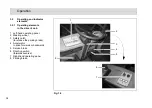
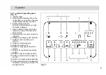
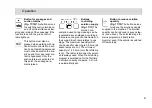
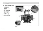
Operating hour
counter
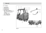
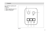
(Fig. 17/5)
The four-digit
LED serves to display
the operating hours.
When the key in the key switch is turned
on, one and then two four-digit codes
appear in succession (for further de-
tails, refer to page 43, Key switch
(Fig. 18/1)). The operating hours ap-
pear after this.
The counter only operates when con-
sumers are switched on (e.g. hydraulic
or brush motor, suction turbine). At the
same time, a red dot flashes at the bot-
tom right of the display.
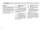
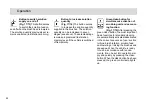
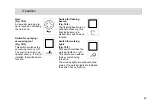
Service indicator
(Fig. 17/5)
The same
LED also serves for a
more accurate determi-
nation of function faults.
If a fault occurs during operation, a four-
digit code (error code) appears in the
service indicator display. At the same
time, the four dots of the error code
flash in the display and a pulsating
acoustic signal is issued. The control
lamp in the functional fault display lights
up red. Section 3.5.1 provides an over-
view of the error codes which help you
clear functional faults yourself. Clear
the fault before starting to use the vehi-
cle again. If you cannot clear the fault
yourself, note down the error code and
inform the authorized Hako dealer re-
sponsible for your vehicle.
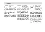
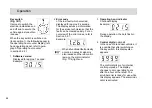
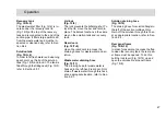
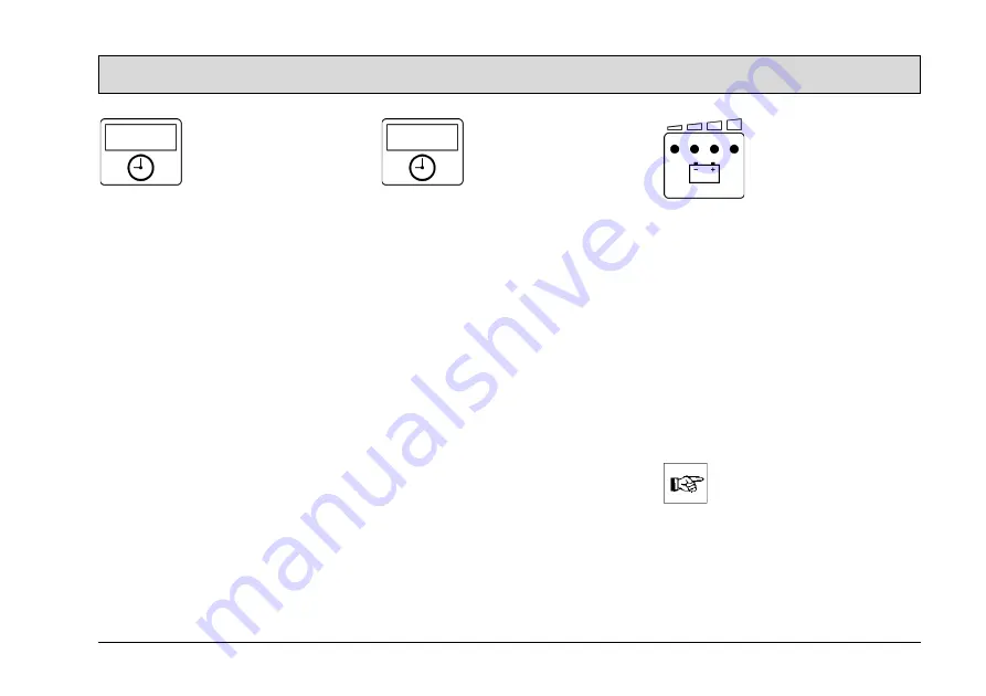
Battery and charge
control indicator
(Fig. 17/6)
After switch-
ing on the key switch, all
four lamps light up when
the battery is fully
charged. As the battery is discharged
during operation, the three right-hand
lamps indicate the level of discharge by
going out in sequence from right to left.
When the left, red lamp flashes, it indi-
cates that work must come to an end.
Approximately three minutes later, the
brushes will return to their home posi-
tion. After a further three minutes, the
suction turbine is deactivated and the
squeegee is raised. When the red lamp
lights up continuously, approximately
one minute remains until the entire ve-
hicle shuts down automatically.
Drive back to the charger in
good time. Take the distance
to the charger into account.

