35
Operation
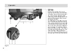
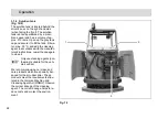
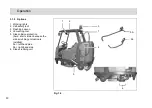
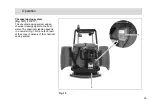
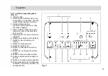
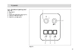
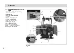
Left-hand operating panel
(Fig. 16/1)
• This operating panel contains all the
buttons for the electronically con-
trolled standard cleaning programs.
• Individual functions can be added or
removed from the cleaning process,
as necessary.
• All the buttons are provided with
clearly descriptive labels.
• The green control lamps in the oper-
ating buttons serve as function indi-
cators.
• The significance and functioning
method of the individual buttons on
this operating panel is described in
section 3.2.2.
Steering wheel
(Fig. 16/2)
• The scrubber drier is steered by the
steering wheel.
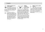
Safety catch
(Fig. 16/3)
• The safety catch serves to release
the parking brake when applied.
• Operating sequence to release
brake:
- Tread on the pedal slightly.
- Press the catch down.
- Release the pedal.
Accelerator to drive forwards and
backwards
(Fig. 16/4)
• The pedal on the right serves to con-
trol the driving speed (as in a normal
vehicle).
• Before actuating the accelerator, use
the driving direction switch
(Fig. 16/6) to set the direction of trav-
el: forwards or reverse.
• Forwards or reverse (according to
the driving direction switch setting):
Press the accelerator forward and
down slowly.
• Release the pedal: The speed is au-
tomatically reduced, slowly. The ve-
hicle rolls to a stop until reaching its
zero setting.
• To stop securely, apply the service
brake (Fig. 16/5).
• The speed for forward drive is ap-
prox. 8 kph and for reverse drive ap-
prox. 4 kph.
• The working speed with the brushes
switches on and squeegee lowered
is approx. 7.5 kph.
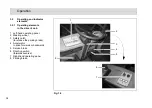
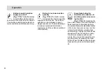
An acoustic warning signal
(buzzer) is issued should the
hydraulic motor overload. At
the same time, the red alarm
lamp (Fig. 16/4) lights up in the
left-hand operating panel
(Fig. 17/1) and the driving
speed is reduced by
approx. 50%. In addition, an
error code appears in the ser-
vice indicator (Fig. 17/5).

