Hakki Pilke 43 Pro Скачать руководство пользователя страница 17

17 / 48 


Hakki Pilke 43 Pro 

Translation 

Version 6-2018 


3.2.2.


Electrical drive 

An  electrically  powered  machine 
is  driven  by  a  15 kW  electric 
motor.  The  IP  rating  of  the 
electric  motor  is  55.  The  fuse 
must  be  at  least  a  32  A  type  C 
fuse. The electrical cable must be 
at  least  5  x  6  mm²,  and  the 
recommended  maximum  length 
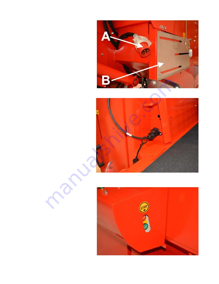
is 25 metres. In order to connect 
the cable, move protective cover 
B of socket A and the angle gear 
and  secure  it  into  a  position 
where it covers the angle gear. 
 
In 

an 

electrically 

powered 

machine, the power cable for the 
electric  controls  is  connected  to 
the  3-pin  socket  on  the  side  of 
the machine. 
 
The electrically powered machine 
is  turned  on  with  the  green 
button  of  the  remote  starter, 
located  in  the  control  panel  in 
the  front  of  the  machine  (Figure 
15).  The  actual  starter  is  located 
below  the  machine’s  control 
panel.  The  starter  features  an 
automatic  fuse  and  a  thermal 
relay  for  the  electric  motor.  The 
thermal  relay  can  be  reset  by 
pressing  the  red  stop  button  on 
the starter. 
 
If  the  electric  motor  rotates  in 
the  wrong  direction  (i.e.  the 
machine  makes  an  abnormal 
noise and the hydraulic functions 
are  inoperable),  the  current 
phase 

is 

incorrect. 

We 

recommend  using  an  extension 
cord  that  allows  you  to  switch 
the current phase, or an adapter.  
 

Note! If the extension cord does 
not  have  a  phase  switch,  the 
electrical 

work 

related 

to 

changing the phase must only be 
performed by an electrician. 


Figure 13. The machine’s electrical drive 


Figure 14. Electrical connector of the electric control device 


Figure 15. The machine’s remote starter 


Содержание 43 Pro

Страница 1: ...sembly operation and maintenance EC Declaration of Conformity Safety instructions Guarantee terms MAASEL N KONE OY Valimotie 1 FI 85800 Haapaj rvi Finland Tel 358 0 8 772 7300 info hakkipilke fi www h...

Страница 2: ...e operating or transport position 12 3 2 Controls 14 3 2 1 Tractor drive 16 3 2 2 Electrical drive 17 3 2 3 Adjusting the log length 18 3 2 4 Using the out feed conveyor 19 3 2 5 Splitting blade adjus...

Страница 3: ...multiplier gear 34 5 3 Changing the hydraulic oil and filters 35 5 4 Conveyor maintenance 36 5 4 1 Replacing and tensioning the in feed conveyor belt 36 5 4 2 Replacing and tensioning the out feed co...

Страница 4: ...of the log and other factors such as branches and burrs make the actual diameter larger and may prevent the log from being fed into the machine The splitting groove is designed for logs up to 60 cm in...

Страница 5: ...ure or operation of the machine or remove protective equipment The operator must wear ear protectors sufficiently tight fitting work clothing and gloves protective goggles and safety footwear Before s...

Страница 6: ...forklift Beware of moving parts Beware of the cardan shaft Beware of the saw chain Beware of the splitting blade Only one person may operate the machine Disconnect the power supply before any mainten...

Страница 7: ...ustained any damage during transport and ensure that all necessary parts are included in the package In the event of any defects or damage contact the retailer immediately Remove any cable ties and st...

Страница 8: ...ing pins must be used to secure them The machine must be placed in the transport position if it is to be moved more than 5 metres Exercise extreme caution when moving the machine in the operating posi...

Страница 9: ...way depending on the size of the tractor 3 Control functions and setting up the machine 3 1 Arranging the machine for operation and transport Before arranging the machine for operation and using it e...

Страница 10: ...Ensure that sufficient room is available to lower the in feed conveyor approx 2 m 2 Release the locking by lifting latch A from shaft B Figure 3 3 Lower the in feed conveyor to the lower position wit...

Страница 11: ...anslation Version 6 2018 5 Turn the log guide plate to the operating position and lock locking pin A into place with cotter pin B Figure 5 Place the in feed conveyor in the transport position in rever...

Страница 12: ...h If you are using a larger conveyor as shown in Figure 8 lower the out feed conveyor hydraulically with control lever E Figure 10 Note Leave sufficient clearance approx 30 cm for the discharge openin...

Страница 13: ...eyor on top of the lower section with the handle s B Figure 8 Note If necessary have two people on either side of the conveyor to lift it 4 Turn the conveyor to the middle position with lever F Figure...

Страница 14: ...ed assist mechanism is in use switch B see Section 4 3 1 B Feed assist mechanism switch Switch in position 1 the feed assist mechanism is turned on continues to feed for the duration of the splitting...

Страница 15: ...HakkiLift OR Out feed conveyor control lever when a larger conveyor is being used Note In this case the accessory is controlled with a valve located in position I in Figure 10 Lever up down the out fe...

Страница 16: ...task for only one person When connecting the machine to the tractor there must be no one in the tractor cabin so as to prevent any accidental contact with the controls Check all the connecting devices...

Страница 17: ...utton of the remote starter located in the control panel in the front of the machine Figure 15 The actual starter is located below the machine s control panel The starter features an automatic fuse an...

Страница 18: ...rectly into the splitting groove 1 Turn the machine off and open the machine s guard 2 Adjust the log length limiter to the desired length by releasing the lock in Figure 16 to the open position as sh...

Страница 19: ...n be turned sideways hydraulically with lever E Figure 10 as follows Lever forwards the conveyor turns to the left Lever backwards the conveyor turns to the right When using a smaller conveyor The con...

Страница 20: ...ntrol lever F Figure 10 Pushing the lever in the front position causes the blade to be lowered while pulling the lever to the back position causes it to rise Logs should always be as centred as possib...

Страница 21: ...o the OFF position as shown in Figure 18 4 Operating the machine 4 1 Performing a test run on the machine The machine may not be used before a test run has been performed and all the functions of the...

Страница 22: ...tomatically raised back up when button C is released and that the cutting chain rotates for the entire time that button C is pressed down c Turn off the machine and disconnect it from the power source...

Страница 23: ...ke 43 firewood processor is equipped with a feed assist mechanism which helps you process logs of equal length by automatically feeding logs forwards whenever the machine s splitting beam moves forwar...

Страница 24: ...ke cutting a thick log impossible On the other hand sawing with an evenly dull chain is inefficient and the cutting chain must be sharpened or replaced see Section 5 1 1 4 3 4 Sawing the last log When...

Страница 25: ...n the guide plates are in automatic mode controller C in Figure 10 is in the front position they immediately rise up when the saw bar starts to cut wood Once the log has been cut and the piece has fal...

Страница 26: ...in series with the in feed conveyor The rollers automatically synchronise with the in feed conveyor when logs are fed with joystick F Figure 10 or when feed assist mechanism B is being used The hoses...

Страница 27: ...e initial position by opening and closing the machine s grey protective cover 2 Lift the splitting blade to the highest possible position with lever F Figure 10 and activate the splitting cycle again...

Страница 28: ...e to lower the splitting blade to the lowest possible position Note the out feed conveyor is A in Figure 22 2 Lower the splitting blade to the lowest possible position If necessary remove pieces of wo...

Страница 29: ...he maximum permitted angle of the out feed conveyor is 40 The running speed of the out feed conveyor can be freely adjusted with adjustment screw H Figure 10 If the conveyor is jammed for any reason t...

Страница 30: ...ration plate D is optimised at the factory in conjunction with the testing of the machine However the adjustment can be changed with adjustment screw C 2 pcs Figure 24 if necessary The optimal speed f...

Страница 31: ...The machine must be disconnected from its power source before any maintenance adjustment replacement or cleaning measures Only use spare parts that are supplied by the manufacturer or your retailer If...

Страница 32: ...e 25 to the OFF position to release the pressure in the automatic cutting chain tensioner 3 Put on gloves and pull the cutting chain downwards at the middle of the beam This will loosen the chain and...

Страница 33: ...Section 5 1 1 2 Remove the beam s fastening bolts A in Figure 26 3 Remove fastening plate C Figure 27 and remove the saw bar from the groove 4 Place the new bar against gear wheel B twist it into the...

Страница 34: ...drain plug G Figure 29 and pour the oil in a suitable container Note The multiplier gear s oil volume is 0 34 litres 4 Close plug G and open filler cap E Figure 29 5 Feed the new oil to the multiplier...

Страница 35: ...type of oil according to the operating conditions If the electric motor is turned on in a cold space the use of an oil with a viscosity of ISO VG 32 and an oil heater accessory is recommended In a tr...

Страница 36: ...able from the side of the in feed conveyor s drive roller until you can pull the belt out from the other end C 7 Lead the rest of the belt under the log press around the rear roller and finally behind...

Страница 37: ...conveyor plates The out feed conveyor plates can be replaced by disconnecting the bolt joints 3 x M8 fastening the plates and replacing the plates with new ones It is recommended that you move the be...

Страница 38: ...e nipples of the guide plates cylinder 2 pcs and the grease nipple of the mechanism in Figure 53 every 50 hours 13 Grease nipple of the hydraulic in feed roller bearing in Figure 53 a every 200 hours...

Страница 39: ...39 48 Hakki Pilke 43 Pro Translation Version 6 2018 Figure 48 Figure 50 Figure 53 Figure 49 Figure 51 Figure 52 Figure 53 a...

Страница 40: ...is 3 5 turns towards the open position from the closed position Increase or decrease the amount as necessary according to the type of wood air temperature and type of oil Before starting always check...

Страница 41: ...ntee is void if the factory settings are changed If you need to change the settings for any reason first contact the manufacturer or retailer and follow their instructions carefully Changing the cartr...

Страница 42: ...correct adjustment value is 250 bar H High pressure valve I Pressure increasing valve Correct adjustment value the hex socket screw is 9 5 mm visible in relation to its head under a protective cup J S...

Страница 43: ...urning mechanism 5 8 Guard mesh safety device The safety device connected to the guard mesh is located behind the relay housing Figure 59 item A The easiest way to access the safety device is to detac...

Страница 44: ...ashed with a high pressure washer as long as the water jet is not aimed directly at the bearings or electrical equipment Always ensure that the machine and the working area are sufficiently clean duri...

Страница 45: ...Subsequent X X X Amount approx 110 l For example ISO VG 32 Oil filter Always when changing oil Number 97348 13921107005357 All levers Lubrication X Lubrication oil Saw bar Check X 18 1 6 mm Cutting bl...

Страница 46: ...akes a loud noise but does not start 2 The thermal relay has tripped 3 Starter fuse triggered 4 The input cable is faulty 1 The gear fuse has blown Replace it 2 Reset the thermal relay with the starte...

Страница 47: ...ceipt that includes the date of purchase Guarantee claims must be submitted to an authorised retailer The guarantee covers Parts damaged in normal use due to faults in the material or workmanship Reas...

Страница 48: ...This guarantee certificate indicates our responsibilities and obligations in full and excludes all other responsibilities 7 EC Declaration of Conformity for the machine Machinery Directive 2006 42 EC...

Отзывы: